Dell Lifecycle Controller Integration Version 3.0 For Microsoft System Center Configuration Manager User's Guide June 2021 Rev.
Notes, cautions, and warnings NOTE: A NOTE indicates important information that helps you make better use of your product. CAUTION: A CAUTION indicates either potential damage to hardware or loss of data and tells you how to avoid the problem. WARNING: A WARNING indicates a potential for property damage, personal injury, or death. © 2014-2021 Dell Inc. or its subsidiaries. All rights reserved. Dell, EMC, and other trademarks are trademarks of Dell Inc. or its subsidiaries.
Contents Chapter 1: Introduction to Dell Lifecycle Controller Integration (DLCI) for Microsoft System Center Configuration Manager................................................................................................... 7 What's new in this release................................................................................................................................................. 7 Existing features and functionalities.....................................................................
Configuration utility.......................................................................................................................................................... 22 Launching the integrated Dell Remote Access Controller console....................................................................... 22 Launching the integrated Dell Remote Access Controller Console from the Task Viewer....................... 22 Task Viewer...........................................................................
Configuring iDRAC profiles for a system..................................................................................................................... 47 Creating an integrated Dell Remote Access Controller profile.........................................................................47 Editing an integrated Dell Remote Access Controller profile............................................................................48 Configuring NICs and CNAs for a system........................................
Dell Connections License Manager status messages...............................................................................................64 ESXi or RHEL deployment on Windows systems moves to ESXi or RHEL collection, but not removed from Windows Managed Collection..........................................................................................................................65 Chapter 8: Related documentation and resources.......................................................................
1 Introduction to Dell Lifecycle Controller Integration (DLCI) for Microsoft System Center Configuration Manager Dell Lifecycle Controller Integration (DLCI) for Microsoft System Center Configuration Manager (Configuration Manager) enables the administrators to leverage the remote enablement capabilities of Dell Lifecycle Controller, available as part of the Integrated Dell Remote Access Controller (iDRAC).
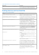
Table 1. New features and functionalities (continued) New feature Description Support for Dell’s 13th generation of PowerEdge servers With this version, you can configure the 13th generations of Dell PowerEdge servers through Integrated Dell Remote Access Controller (iDRAC) with Lifecycle Controller (LC) Existing features and functionalities Table 2.
Table 2. Features and functionalities (continued) Feature Functionality You can also compare the applied NIC/CNA profiles against the NIC/CNA configurations of the systems and generate comparison reports. Configure iDRAC profiles for a system or collection You can define iDRAC configurations for a system and save it as part of a hardware configuration profile of the system.
Table 2. Features and functionalities (continued) Feature Functionality Support for configuring Storage area network (SAN) boot attributes Allows you to configure SAN boot attributes. Support for exporting the system profiles before and after hardware configuration Allows you to back up the system profiles for a collection of systems by exporting the profile to an iDRAC vFlash card or a network share.
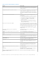
Table 3. Compatible operating systems for WinPE (continued) Configuration Manager WinPE version Operating system ● Windows Server 2012 R2 ● Windows Server 2016 Configuration Manager 2012 R2 5.0 ● Windows Server 2008 R2* ● Windows Server 2012 ● Windows Server 2012 R2 Configuration Manager 2012 SP1 4.0 ● Windows Server 2008 R2* ● Windows Server 2012 Configuration Manager 2012 3.0 ● Windows Server 2008 ● Windows Server 2008 R2 Legend: * — For Windows Server 2008 R2 support, visit support.microsoft.
2 Use case scenarios This section describes typical use cases and tasks that you can perform with DLCI for Microsoft System Center Configuration Manager (Configuration Manager).
Creating, editing, and saving a RAID profile of a system You can create, edit, and save the RAID profile of a system and apply it when you deploy an operating system to a collection of systems on the Configuration Manager console. Prerequisites ● Common prerequisites on page 12 ● RAID controller and firmware that supports Local Key Management The following steps outline the workflow sequence: 1. Launch the System Viewer utility on the Configuration Manager console for a particular system.
2. Select Firmware Inventory, Compare, and Update from the System Viewer utility or Config Utility. 3. For a single system, see Comparing and updating firmware inventory on page 51. 4. For a collection, see Comparing and updating firmware inventory for systems in a collection on page 37. Deploying operating system on collection You can use DLCI for Configuration Manager to deploy an operating system on a collection of systems on the Configuration Manager console.
○ With a minimum free space of 384 MB available ● Administrator privileges on the iDRAC of the target systems Before you begin Before you begin exporting the system profile for a single system or a collection: ● Make sure that operations such as firmware update, operating system deployment, and firmware configurations are not running.
Before you begin Before you begin importing the backup file to a system or collection, ensure that: ● User Data is not present in the backup image file. If you overwrite the existing configuration with the backup image file, the user data is not restored. ● During import, operations such as firmware update, operating system deployment, and firmware configurations are not running. ● After you deploy the operating system using Lifecycle controller, the OEMDRV is open for 18 hours.
3. For a single system, see Viewing Lifecycle Controller logs on page 52. 4. For a collection, see Viewing and exporting Lifecycle Controller logs for a collection on page 39. Working With NIC or CNA Profiles You can configure the different attributes of specific network interface cards (NICs) or converged network adapters (CNAs) embedded in the system and save them to a profile. You can create and edit NIC or CNA profiles using the System Viewer utility.
3 Using Dell Lifecycle Controller Integration This chapter discusses the various operations that you can perform after you install DLCI on Configuration Manager. Before you begin using DLCI for Configuration Manager, ensure that the target system is auto-discovered and present in the All Dell Lifecycle Controller Servers collection on the Configuration Manager console.
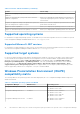
2. In Dell Connections License Manager Configuration Utility, click Licensing Configuration. 3. In Licensing Configuration, provide the license server location, user name in domain\username format, and password. The default port numbers are 8543 and 8544. To apply the current logged on user credentials, select Use current logged on user credentials. 4. To test connection, click Test Dell Connections License Manager. 5. Click Apply. 6. Click Launch Dell Connections License Manager Web Console.
Applying Drivers from the task sequence Based on the operating system you want to deploy, either apply drivers from the Lifecycle Controller or the Configuration Manager repository. Use the drivers in the Configuration Manager repository as backup.
1. In Configuration Manager Version 1610, Configuration Manager 2012 SP2, Configuration Manager 2012 R2 SP1, Configuration Manager 2012 R2, Configuration Manager 2012 SP1, or Configuration Manager 2012 under Software Library, right-click Task Sequences and select Create Task Sequence Media. NOTE: ● Ensure that you manage and update the boot image across all distribution points before starting this wizard.
Configuration utility The Configuration Utility allows you to perform various operations from the source system to the entire collection of Dell systems discovered under All Dell Lifecycle Controller Servers on the Configuration Manager console. This utility works on a one-to-many relationship and uses the Remote Enablement feature of the Lifecycle Controller present on Dell systems. You can perform various operations on all the target systems at one time. To launch the Configuration Utility: 1.
Task Viewer The Task Viewer is an asynchronous component that hides in the task bar and displays the status of tasks handled by the DLCI for Configuration Manager. All the tasks are displayed in the Task Viewer. For example, long-running tasks such as operating system deployment, or applying firmware updates to systems. The Task Viewer maintains a queue of tasks and displays up to twenty tasks at one time.
Validating a Dell factory-issued Client Certificate on the Integrated Dell Remote Access Controller for auto-discovery This security option requires that a system being discovered by the provisioning website during the discovery and handshake process has a valid factory-issued client certificate which is deployed to the iDRAC. This feature is enabled by default. To disable the feature, run the following command: C:\Program Files (x86)\Dell\DPS\ProvisionWS\bin\import.
Defining rules with the Array Builder You can define rules to match configurations based on the following: ● Detected slot number that the controller is in or just the embedded controller, if any. ● Number of disks that are attached to the controller. ● Apply a blanket configuration to any controller the Array Builder finds. You can also apply configuration rules based on the RAID profiles detected on the server.
Adding a Controller To add a controller: 1. Select a controller from the list, or select an embedded controller. The Controllers drop-down menu to your left is enabled. 2. Click Controllers → New Controller. The Controller Configuration window is displayed. 3. Under Controller Selection Criteria, select from the following options: ● Select the controller located in slot — Enter the slot number of the controller.
Editing a variable condition To edit a variable condition: 1. Select the variable condition and click Variables → Edit Variable Condition. The Variable Condition Configuration window is displayed where you can make changes to your variable condition. 2. Click OK to apply the variable condition, or Cancel to return to Array Builder. Deleting a variable condition To delete a variable condition: 1. Select the variable condition and click Variables → Delete Variable Condition.
NOTE: Array Builder does not support creating logical drives of sizes 10, 50, and 60 GB, and does not support creating logical drives under Non-RAID groups. Adding a new logical drive To add a new logical drive under an array: 1. Select the array and click Logical Drives → New Logical Drive. The Logical Drive Settings window is displayed. 2. Under Create a logical drive, enter the exact number of gigabytes the logical drive must contain. 3.
● Hot spare (only for the current array) ● Global hot spare (all arrays) Deleting a disk To delete a disk, click on the disk and select Disks > Delete Disk. Importing a profile This menu item allows you to search for, and import an existing Array Builder profile. The XML profile file must be properly formatted. If it is not formatted correctly, Configuration Manager automatically modifies the XML file and sends a notification of the change.
4 Using the Configuration Utility This section describes the various operations that you can perform with the Dell Lifecycle Controller Configuration Utility. You can use the Config Utility from the Configuration Manager console to: ● Create a new Lifecycle Controller boot media to deploy operating systems remotely. For more information, see Creating a Lifecycle Controller boot media on page 30. ● Configure hardware and deploy the operating system on the target systems in the collection.
NOTE: You can launch Config Utility for any collection. 2. In the Dell Lifecycle Controller Configuration Utility window, select Create new Lifecycle Controller Boot Media on the left-hand pane. 3. Click Browse and select the bootable ISO that you created. For more information, see Creating a task sequence media bootable ISO on page 20. 4. Specify the folder or path to save the Dell Lifecycle Controller boot media.
● Red Hat Enterprise Linux ● ESXi NOTE: After deploying non-windows operating systems, the service tag of the system name is displayed as host name in Configuration Manager console. ESXi installation is supported only on a hard disk for this release. For ESXi, Red Hat Enterprise Linux, the operating system is installed on the first disk with default configuration. For Red Hat Enterprise Linux, the following are set: ● Language is set to US ● Keyboard is set to US (U.S.
Hardware configuration and OS deployment workflow To deploy the operating system to a collection: 1. In Configuration Manager Version 1610, Configuration Manager 2012 SP2, Configuration Manager 2012 R2 SP1, Configuration Manager 2012 R2, Configuration Manager 2012 SP1, or Configuration Manager 2012, in Device Collections, right-click any appropriate Dell collection and select Dell Lifecycle Controller > Launch Config Utility. 2.
NOTE: If you have set a default share location for the Lifecycle Controller boot media, the default location populates automatically. 19. Type the user name and password for accessing the share where the Dell Lifecycle Controller bootable media is located. 20. Click Reboot Targeted Collection. This selection sends the jobs for each system in the collection to the Task Viewer. To view the current tasks in the queue and their status, open the Task Viewer by clicking the Dell icon on the task bar.
Configuring RAID To configure RAID: 1. Click Browse and select the RAID profile that you created using the System Viewer utility. This profile is applied during the operating system deployment process. For more information on creating RAID profiles, see Using the Array Builder. 2. Click Next to configure network adapters.
Applying an integrated Dell Remote Access Controller profile on a collection To configure iDRAC and apply an iDRAC profile on a collection: 1. Click Browse and select the iDRAC profile that you created using the System Viewer utility. This profile is applied during the hardware configuration process. For more information on creating iDRAC profiles, see Creating an integrated Dell Remote Access Controller profile on page 47. 2.
NOTE: If there is an error while applying an iDRAC profile, the operating system deployment process stops. Comparing and updating firmware inventory for systems in a collection This feature enables you to retrieve, compare, and update firmware inventory on the Dell systems with Lifecycle Controllers in a collection. NOTE: To compare and update firmware remotely, you must ensure that the Dell systems have iDRAC6 firmware version 1.5 or higher. For more information on upgrading to firmware version 1.
1. In Configuration Manager Version 1610, Configuration Manager 2012 SP2, Configuration Manager 2012 R2 SP1, Configuration Manager 2012 R2, Configuration Manager 2012 SP1, Configuration Manager 2012, in Device Collections, right-click All Dell Lifecycle Controller Servers and select Dell Lifecycle Controller > Launch Config Utility. 2. On the Dell Lifecycle Controller Configuration Utility, select Hardware Inventory.
A list of iDRACs that are discovered on the network appears along with their communication status. To change the user name and password credentials, and to indicate the change, a series of WS-MAN commands are sent to all systems with iDRAC that are in the collection. 5. After the update is complete, click Export to CSV to export the results in CSV format. Provide the location on your local drive. or Click Copy to Clipboard to copy the results to the clipboard and save it in plain text format.
● Configure Part Replacement properties for a collection. For more information, see Configuring Part Replacement properties for a collection on page 40. Exporting the system profiles in a collection You can use this option to take a backup of the system configurations of all the systems in a collection. To launch the Platform Restore screen for a collection: 1.
Comparing NIC or CNA profiles against systems in a collection This feature enables you to generate a comparison report of how a NIC/CNA profile is applied to systems and identify any mismatches from the target systems. To generate a comparison report: 1.
5 Using the Import Server Utility This section describes the various activities that you can perform using the Import Server utility. This utility is installed when you install DLCI for Configuration Manager. For information on installing Dell Lifecycle Controller Integration for Configuration Manager, see the Installation Guide.
Licensing Information Licensed nodes: Number for nodes provided. Nodes in use: Number of nodes assigned to servers. The managed server is displayed in green color. 6. Click Next and select the servers that you want to import. By default, all systems where the Authentication status is Success are selected. 7. Click Save As to save the report as a .CSV file in any location. 8. Specify the Target Collection under which you want the imported servers to be displayed and click Next. 9.
● Variable Name — the name of the variable. ● Value in the .CSV file — the value of the variable in the .CSV file. If the variable is not present in the file, this column displays the value NA. ● Value in the System — the value of the variable in the system. If the variable is not present on the system, this column displays the value NA. ● Action — the action to be taken for the variable. This action always gives precedence to the variables and the values present in the .CSV file. Table 6.
6 Using the System Viewer Utility This chapter describes the operations that you can perform with the System Viewer Utility. You can use the System Viewer Utility to: ● ● ● ● ● ● ● ● ● View and edit the hardware configuration. View and edit the RAID configuration. Create and edit iDRAC configuration profiles for your system. Create configurations for network adapters such as NICs and CNAs and save them to a profile. Create configurations for FC HBA cards and save them as a profile.
NOTE: You can leave the BIOS attributes in a profile unchecked. If you do not select any of the BIOS attributes in a profile, then only the boot sequence information is considered when you import the profile. 3. Click Save As Profile to save the profile as an XML file. Editing an existing profile To edit an existing profile: 1. In the BIOS Configuration screen, select Edit an Existing Profile, and click Browse to browse for the profile. 2. Select the profile that you want to edit and click Next.
After you manually map SAN boot device in server, it is visible as hard disk drive sequence. To change the boot sequence for SAN boot device, use Move Up to move up the SAN boot device in the hard disk drive sequence until it is the first boot device in the hard disk drive sequence.
● To edit a user account, select the account on the grid and click Edit, or double-click the user account. The Edit User screen is displayed. NOTE: You cannot edit the user account that DLCI uses to access the iDRAC of the system. 7. Specify the following details: ● General Details — Type the user name and password. You must specify the password when you create or edit a user account. ● IPMI LAN user Privilege granted — Select the type of user from the drop-down list to grant the IPMI LAN user privilege.
3. Click Add to add an adapter. 4. In ● ● ● the Add Adapter dialog box, perform the following: Select the Adapter type from the drop-down list. Select the adapter location and specify the slot number. Click OK. The adapter is now added to the Network Adapter Configuration screen. 5. If you want to remove any of the adapters from the profile, select the adapter and click Remove. 6. Select the adapter and click Configure to configure it.
● Copy settings from port — to copy the port settings from a port that is already configured. Proceed to step 7 if you are copying the port settings. 6. You need to choose the personalities for each partition on the port, enter bandwidth and configure settings for each personality. One port can have up to four partitions with one personality assigned to each partition. Under Personalities and Settings, select the personality against each partition and set the minimum and maximum bandwidth.
1. On the System Viewer utility, click Network Adapter Configuration. 2. Select Edit an Existing Profile. 3. Click Browse and navigate to the location where you have saved the NIC profiles. 4. Select the profile that is saved as a .XML file and click Next. The Network Adapter Configuration screen displays the adapters that you have configured in the profile. 5. Select the adapter you want to edit and click Configure. For more information on configuring the adapter, see Configuring adapters on page 49. 6.
● Downgrade: Indicates the downgrade of the current version. ● Not Updatable: Indicates the baseline version is not updatable. ● Not Available: Indicates the baseline version is not available. 5. You can filter the information based on any of the baseline details, set schedule based on the available options and then click Update to update your system with the latest firmware. ● start now — to start the update. ● start on next reboot — to start the update when the target system reboots.
Table 7. Lifecycle Controller log details (continued) Column Description No. This is the sequence number of the log. Category The category of the Lifecycle Controller Log. For example, Configuration Service, iDRAC, Inventory, and so on. ID This is the ID associated with an error message. Click the hyperlink to get more information on the error and the recommended action. You can periodically download the latest message registry from the Dell support website available at Dell.com/support/manuals.
Downloading and updating the 11th and 12th generation message registry Dell recommends that you close all the DLCI utilities such as the System Viewer Utility, Config Utility, and Task Viewer before you download and extract the message registry. The message registry does not contain detailed information for user defined Logs of type Work notes (for example, WRK001) or Logs with category Other.
NOTE: For the PowerEdge 11G systems, the Slot Length and Slot Type fields may show the status as Not Applicable instead of Unknown. Platform restore for a system You can use this option on the System Viewer utility to perform the following functions: ● ● ● ● Export a system profile. For more information, see Exporting the system profile on page 55. Import a system profile. For more information, see Importing the system profile on page 56. Manage profiles.
4. Enter a backup file passphrase. This is used to lock the encrypted portions of the backup file. For a successful backup operation, the backup file passphrase has to be in a specific format, which is as follows: ● the passphrase must contain a minimum of 8 characters. ● the passphrase must contain the following combination of characters— at least 1 title case character, at least 1 lower case character, at least 1 special character, and at least one numeric character.
5. Click Next. While importing the backup file, you can choose to retain the current RAID controller configuration, or restore the backed up configuration from the backup file. Choose one of the following options: ● Preserve: Retains the existing RAID controller configuration. ● Delete: Deletes the existing RAID controller configuration and import the configuration from the backup file. NOTE: This operation does not restore content that was on the virtual disk during the backup.
A task is submitted to the Task Viewer. You can launch the Task Viewer to view the status of the task. The task configures the Lifecycle Controller of the system with the Part Replacement configuration. This configuration takes effect when you replace any part for the system. If you have updated the Part Replacement Attributes, sometimes the updates are not set immediately. Wait for couple of minutes and check to see if the updates are set.
7 Troubleshooting This topic list the issues and steps to troubleshoot them.
Dell auto-discovery network setup specification For information on auto-discovery error messages, descriptions, and response actions, see the Dell Auto-Discovery Network Setup Specification document at delltechcenter.com Upgrade or repair issues If you have upgraded or repaired the Dell Server Deployment Pack after installing Dell Lifecycle Controller Integration for ConfigMgr 1.2 or later: 1. Copy the CustomReboot.vbs from [ConfigMgrRoot]\AdminUI\XmlStorage\Extensions\Bin\Deployment\ Dell\PowerEdge\LC\ to
To avoid this issue, ensure that you enable Spanning Tree and Fast Link on the network switch. Issue 2 Issue: If the Lifecycle Controller of a system is in use, the system is not discovered. Resolution: If a system does not show up in a collection, verify whether the log file contains the following error message: Lifecycle Controller in use. If it contains the error message: 1. Ensure that the system is not in Power On Self Test (POST) state.
Issue 8 Issue: If the Lifecycle Controller on the target system is locked by another process, the following error message is displayed in the DLCTaskManager.log file: Lifecycle Controller is being used by another process. Resolution: Ensure that the iDRAC of your system is not in POST state.
To re-enable the Apply option: 1. Right-click the task sequence and select Edit. 2. Select Restart in Windows PE. In the Description section, type any character and delete it so the change is not saved. 3. Click OK. This re-enables the Apply option. Issue 15 Issue: The System Viewer Utility does not display the latest RAID configuration. Resolution: When you are viewing the RAID configuration for a system using the System Viewer Utility, the information is cached.
Issue 22 Issue: When you continuously add Lifecycle Controller Logs, or one or more of the components continuously create log entries, you may not view the Lifecycle Controller Logs for the collection. Resolution: To view the Lifecycle Controller Logs, click Refresh on the Lifecycle Controller Logs screen after waiting for a short period. Issue 22 Issue: Creation of unattended operating system media takes a long time in a non-windows operating system deployment.
Table 9. Dell Connections License Manager status information (continued) Alert Message Alert State Cause Resolution The Dell Connections License Manager details are not configured. Warning The Dell Connections License Manager details are not configured. Launch Dell Connections License Manager Configuration Utility and configure Connections License Manager for DLCI.
8 Related documentation and resources For more information on Configuration Manager such as installation, features, and functionalities, see the Microsoft TechNet site at technet.microsoft.com. In addition to this guide, you can access the following guides available at Dell.com/support/manuals. On the Manuals page, click Software and Security > System Management.
2. Click Browse all products. 3. From the All products page, click Software, and then click the required link. 4. Click the required product and then click the required version. Using search engines, type the name and version of the document in the search box.