Dell Lifecycle Controller Integration Version 2.
Notes, Cautions, and Warnings NOTE: A NOTE indicates important information that helps you make better use of your computer. CAUTION: A CAUTION indicates either potential damage to hardware or loss of data and tells you how to avoid the problem. WARNING: A WARNING indicates a potential for property damage, personal injury, or death. Copyright © 2014 Dell Inc. All rights reserved. This product is protected by U.S. and international copyright and intellectual property laws.
Contents 1 Introduction..................................................................................................................................7 What's New in This Release.....................................................................................................................................7 Existing Features and Functionalities....................................................................................................................... 8 Supported Operating Systems..........
Configuring Target Systems................................................................................................................................... 18 To Enable CSIOR for Earlier Server Generations:............................................................................................ 18 To Enable CSIOR for PowerEdge 12G Servers:................................................................................................ 18 Auto-Discovery and Handshake......................................
Exporting the System Profiles in a Collection.................................................................................................. 41 Importing the System Profiles in a Collection.................................................................................................. 42 Configuring Part Replacement Properties for a Collection..............................................................................42 Comparing NIC or CNA Profiles Against Systems in a Collection....................
Upgrade or Repair Issues....................................................................................................................................... 63 Troubleshooting the Viewing and Exporting of Lifecycle Controller Logs..............................................................63 Issues and Resolutions...........................................................................................................................................64 Issue 1 ..........................................
1 Introduction Dell Lifecycle Controller Integration (DLCI) For Microsoft System Center 2007 Configuration Manager and Microsoft System Center 2012 Configuration Manager enables the administrators to leverage the remote enablement capabilities of Dell Lifecycle Controller, available as part of the Integrated Dell Remote Access Controller (iDRAC).
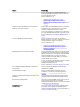
New Support Functionality previous version of Dell Lifecycle Controller Integration are supported for Dell PowerEdge 12G servers. Lifecycle Controller support for DLCI You can configure Dell PowerEdge 11G servers using Dell Lifecycle Controller Integration through Lifecycle Controller version 1.6. All the features of the previous version of Dell Lifecycle Controller Integration are supported for Dell PowerEdge 11G servers. Existing Features and Functionalities Table 2.
Feature Functionality You can also compare the applied NIC/CNA profiles against the NIC/CNA configurations of the systems and generate comparison reports. For more information, see: • • • Configuring NICs and CNAs for a System. Applying a NIC or CNA Profile on a Collection. Comparing NIC Or CNA Profiles Against Systems in a Collection.
Feature Functionality Config Utility This feature enables you to configure a collection of systems by using the remote enablement capabilities of Lifecycle Controller. For more information, see Using the Configuration Utility. Launching the iDRAC Console This feature enables you to launch the iDRAC console from the Task Viewer and from a system in the collection that contains Dell PowerEdge 11G or 12G systems. For more information, see Launching the Integrated Dell Remote Access Controller Console.
Use Case Scenarios 2 This section describes typical use cases and tasks that you can perform with Dell Lifecycle Controller Integration for Microsoft System Center Configuration Manager (ConfigMgr). Common Prerequisites Before working on the user scenarios, it is recommended that you complete the following prerequisites. • • • • • • In Configuration Manager 2012, make sure that the system is discovered and present under Assets and Compliance → Devices → All Dell Lifecycle Controller Servers.
Prerequisites • Common Prerequisites • RAID controller and firmware that supports Local Key Management Workflow 1. Launch the System Viewer utility on the Configuration Manager console for a particular system. For more information, see System Viewer Utility. 2. Select RAID Configuration on the System Viewer utility to load the RAID configuration of the system. For more information, see Viewing and Configuring RAID. 3. Launch Array Builder to create a RAID profile.
• Install Dell Server Deployment Pack version 2.1 with the latest service packs, available as an plugin and then create a task sequence using Dell Server Deployment Pack to apply drivers from Lifecycle Controller. For more information, see Applying Drivers From Lifecycle Controller. • Apply drivers from a Configuration Manager repository, for more information, see Dell Server Deployment Pack documentation available at dell.com/support/manuals.
Before You Begin Before you begin exporting the system profile for a single system or a collection: • Make sure that operations such as firmware update, operating system deployment, and firmware configurations are not running. • After you deploy the operating system using Lifecycle controller, the Original Equipment Manufacturer Drive (OEMDRV) is open for 18 hours as the Lifecycle Controller does not have the status of the operating system installation.
Before You Begin Before you begin importing the backup file to a system or collection, ensure that: • User Data is not present in the backup image file. If you overwrite the existing configuration with the backup image file, the user data is not restored. • During import, operations such as firmware update, operating system deployment, and firmware configurations are not running. • After you deploy the operating system using Lifecycle controller, the OEMDRV is open for 18 hours.
Workflow 1. To view the Lifecycle Controller logs of a single target system, launch the System Viewer utility. To view the Lifecycle Controller logs of a collection of systems, launch the Config Utility. For more information, see System Viewer Utility or Configuration Utility. 2. Select View Lifecycle Controller Logs on the System Viewer utility or the Config Utility. 3. For a single system, see Viewing Lifecycle Controller Logs. 4.
Using Dell Lifecycle Controller Integration 3 This chapter discusses the various operations that you can perform after you install Dell Lifecycle Controller Integration on Microsoft System Center Configuration Manager (Configuration Manager). Before you begin using Dell Lifecycle Controller Integration for Configuration Manager, ensure that the target system is auto-discovered and present in the All Dell Lifecycle Controller Servers collection on the Configuration Manager console.
Configuring Dell Lifecycle Controller Integration With Dell Connections License Manager Confirm that these prerequisites are available: • Site Server or Configuration Manager console components of Configuration Manager 2007 or Configuration Manager 2012 are installed and configured. • Dell Connections License Manager application is installed and configured with a valid license. To configure Dell Lifecycle Controller Integration with Dell Connections License Manager. 1.
Auto-Discovery and Handshake The auto-discovery and handshake feature enables the iDRAC on target systems to locate the provisioning service and establish communication with the Site Server. The Dell Provisioning service provisions a management account and updates Configuration Manager with the new system. The Dell Lifecycle Controller Utility (DLCU) for Configuration Manager uses the provisioned account to communicate with the iDRAC of target systems, to invoke the enabled features.
Applying Drivers From the ConfigMgr Repository To apply drivers from the ConfigMgr repository: Apply driver packages for the selected operating systems in ConfigMgr. For more information on applying driver packages, see Dell Server Deployment Pack for Microsoft System Center Configuration Manager User’s Guide available at dell.com/support/manuals.
10. On completion, close the wizard. System Viewer Utility The System Viewer utility allows you to perform various operations from the source system to a single target system discovered under All Dell Lifecycle Controller Servers on the Configuration Manager console. This utility works on a one-to-one relationship and you can perform the operations on target systems one at a time.
• Overview • Create new Lifecycle Controller Boot Media • Hardware Configuration and Deploy Operating System • Firmware Inventory, Compare, and Update • Hardware Inventory • Session Credentials, Verify Communication • Modify Credentials on Lifecycle Controllers • View Lifecycle Controller Logs • Platform Restore • Network Adapter Comparison Report For more information on using the Configuration Utility, see Using the Configuration Utility.
running tasks such as operating system deployment, or applying firmware updates to systems. The Task Viewer maintains a queue of tasks and displays up to twenty tasks at one time. The task viewer displays the following details: • Name: Displays the name or the service tag of the system on which the task is running. • Task: Displays which task is running on the system. • Status: Displays the status of the task running on the system. • Start Date/Time: Displays the date and time when the task started.
Validating a Dell Factory-Issued Client Certificate on the Integrated Dell Remote Access Controller for Auto-Discovery This security option requires that a system being discovered by the provisioning website during the discovery and handshake process has a valid factory-issued client certificate which is deployed to the Integrated Dell Remote Access Controller. This feature is enabled by default. To disable the feature, run the following command: C:\Program Files (x86)\Dell\DPS\ProvisionWS\bin\import.
When a controller is created, a default variable condition, array and disk(s) are created to ensure a valid configuration. You can choose to leave the controller un-configured with disks set to non-RAID, or you can add arrays or perform other actions. Defining Rules With the Array Builder You can define rules to match configurations based on the following: • Detected slot number that the controller is in or just the embedded controller, if any. • Number of disks that are attached to the controller.
Controllers Controller elements contain variable condition elements. Controllers can be one of several configuration types: • The embedded controller • A controller in slot "X" • Any controller with "X" disks • Any controller with "X" disks or more • All remaining controllers Adding a Controller To add a controller: 1. Select a controller from the list, or select an embedded controller. The Controllers drop-down menu to your left is enabled. 2. Click Controllers→ New Controller .
NOTE: Dell Lifecycle Controller Integration for ConfigMgr does not support variables created in an encrypted format. Adding a New Variable Condition To add a new variable condition: 1. Under an embedded controller, expand Embedded Controller, and select [No variable conditions defined]. 2. Click Variables→ New Variable Condition. The Variable Condition Configuration window is displayed. 3.
Deleting an Array To delete an array: 1. Select the array and click Arrays→ Delete Array. A message is displayed that all the attached disks will be deleted. 2. Click Yes to delete or No to cancel. Logical Drives also known as Virtual Disks Logical drives can be present on RAID arrays and non-RAID groups. You can configure them by specifying the size (in GB) or consume all available (or remaining) space in the array.
they can only be moved from array to array (or the non-RAID group). If the controller specifies a minimum number of disks, you can add or remove disks, but you cannot remove disks below the lower limit of the controller configuration. Adding a New Disk To add a new disk to an array, select the array and click Disks → New Disk.
Using the Configuration Utility 4 This section describes the various operations that you can perform with the Dell Lifecycle Controller Configuration Utility. You can use the Config Utility from the ConfigMgr console to: • Create a new Lifecycle Controller boot media to deploy operating systems remotely. For more information, see Creating a Lifecycle Controller Boot Media. • Configure hardware and deploy the operating system on the target systems in the collection.
• In Configuration Manager 2007, under Computer Management → Collections. Right-click All Dell Lifecycle Controller Servers and select Dell Lifecycle Controller → Launch Config Utility. NOTE: You can launch Config Utility for any collection. 2. In the Dell Lifecycle Controller Configuration Utility window, select Create new Lifecycle Controller Boot Media on the left-hand pane. 3. Click Browse and select the bootable ISO that you created.
Deploying Operating Systems You can deploy Windows and non-Windows operating systems on a collection and the operating system deployment is only supported for deploying operating systems on multiple servers. During the operating system deployment, the status and progress of installation is displayed in the DLCI task viewer. After installing the operating system, the system is added to a collection and is identified as Managed Dell Lifecycle Controller Servers .
• oddjob • sgpio • certmonger • pam_krb5 • krb5-workstation • perl-DBD-SQLite For deploying ESXi, use the Dell customized ISO available at dell.com/support/manuals. Provide the ISO share on a NFS share. This share is used by DLCI to extract the ISO and create a custom ISO. The custom ISOes are saved on the same share. It is recommended that the machine with the NFS share is not connected to the Internet.
12. Select Do not deploy operating system in the advertisement screen if you want to skip deploying the operating system on the collection. In this case, the Next button is disabled and you can directly click Reboot targeted collection. The hardware configuration tasks are submitted based on the selections you made in the previous steps and you can view the status of tasks on Task Viewer. 13.
Updating Firmware During OS Deployment To update the firmware: 1. Select one of the following options: • • Dell PDK catalog — to specify a Dell PDK catalog that you can use to compare the firmware inventory. To specify a PDK catalog, do the following: – Click Browse to navigate to the file location where you have saved the catalog. Ensure that the catalog resides on a CIFS share that is accessible to the Dell Lifecycle Controller of the system.
To configure Network Adapters and apply a NIC/CNA profile on a collection: 1. Click Browse and select the NIC/CNA profile that you created using the System Viewer utility. This profile is applied during the hardware configuration process. For more information on creating NIC/CNA profiles, see Creating a NIC or CNA Profile. 2.
Table 4. iDRAC Profile Settings S.No Target Server Profile Settings What is Applicable 1. Rack and Tower systems All four types of attributes are configured. All attributes in the Integrated Dell Remote Access Controller profile. 2. Blade systems All four types of attributes are configured. • • • 3. All attributes in Common IP settings. All attributes in IPv4 settings. Only vLAN ID and vLAN priority attributes from Advanced LAN settings. 3.
NOTE: To compare and update firmware remotely, you must ensure that the Dell systems have iDRAC6 firmware version 1.5 or higher. For more information on upgrading to firmware version 1.5, see the Integrated Dell Remote Access Controller 6 (iDRAC6) Version 1.5 User Guide available at dell.com/support/manuals. To compare and update firmware inventory: 1. From the Configuration Manager console: • In Configuration Manager 2012, under Device Collections.
Viewing the Hardware Inventory You can use the Config Utility to view the hardware inventory details of all the systems in the collection. To view the hardware inventory: 1. From the Configuration Manager console: • In Configuration Manager 2012, under Device Collections. • In Configuration Manager 2007, under Computer Management → Collections. Right-click All Dell Lifecycle Controller Servers and select Dell Lifecycle Controller → Launch Config Utility. 2.
NOTE: It is recommended that you modify the credentials on the Lifecycle Controller as well as the ConfigMgr database simultaneously. To modify the credentials on Lifecycle Controllers: 1. From the Configuration Manager console: • In Configuration Manager 2012, under Device Collections. • In Configuration Manager 2007, under Computer Management → Collections. Right-click All Dell Lifecycle Controller Servers and select Dell Lifecycle Controller → Launch Config Utility. 2.
4. In the New Account Information window, enter the new user name and new password. Confirm the new password and click OK. You have updated the new user name and password credentials in the Configuration Manager Database. Viewing and Exporting Lifecycle Controller Logs for a Collection You can view the Lifecycle Controller logs for a collection in a readable format and save or export the logs to a .CSV file in a Unified Naming Convention (UNC) or Common Internet File System (CIFS) share.
When the backup files for a collection are created, the backup file for each system is created with the prefix you specify, followed by the service tag of the system. This is to manage the backup files created to ease out the restoring process. Importing the System Profiles in a Collection You can import the system profiles/backup files that you have created. This option is applicable only if you have created backup images/profiles of the systems in the collection.
• In Configuration Manager 2012, under Device Collections. • In Configuration Manager 2007, under Computer Management → Collections. Right-click All Dell Lifecycle Controller Servers and select Dell Lifecycle Controller → Launch Config Utility. 2. Select the Network Adapter Comparison Report option. 3. On the Network Adapter Comparison Report screen, click Browse and select the NIC/CNA profile file that you have applied to the collection. 4.
Using the Import Server Utility 5 This section describes the various activities that you can perform using the Import Server utility. This utility is installed when you install Dell Lifecycle Controller Integration for Microsoft System Center Configuration Manager. For information on installing Dell Lifecycle Controller Integration for ConfigMgr, see the Installation Guide.
– 4. New Line: 72.16.1.5 – New Line: 172.16.1.45 Click Next. The Integrated Dell Remote Access Controller (iDRAC) Authentication process verifies the iDRAC credentials you have provided when you install Dell Lifecycle Controller Integration for Configuration Manager against each of the iDRAC IP addresses you have specified. The grid displays the IP Address, name of the server, and the status of the authentication. You can provide user credentials authenticated on active directory.
5. Click Close. Importing System Variables To import system variables from an external file saved in .CSV format: 1. From Configuration Manager: • • On the Configuration Manager 2012 console: 1. Navigate to Assets and Compliance and right-click Devices. 2. Select Dell Lifecycle Controller → Import Dell PowerEdge Server. In the Configuration Manager 2007 console: 1. Navigate to Operating System Deployment → Computer Association. 2. 2.
Table 5. Action And Description 6. Action Description ADD Add the variable to the target system. Indicates that the variable is present on the file and not available on the system. DELETE Delete the variable from the target system. Indicates that the variable is not present on the file but available on the system. UPDATE Update the variable on the target system with the value from the .CSV file. Indicates to replace the variable on the system with the variable on the file. NONE Take no action.
Using the System Viewer Utility 6 This chapter describes the operations that you can perform with the System Viewer Utility. You can use the System Viewer Utility to: • View and edit the hardware configuration. For more information, see Viewing and Editing BIOS Configuration. • View and edit the RAID configuration. For more information, see Viewing and Configuring RAID. • Create and edit Integrated Dell Remote Access Controller configuration profiles for your system.
Creating a New Profile To create a new profile: 1. In the BIOS Configuration screen, select Create a New Profile and click Next. The BIOS Attributes tab displays the BIOS attributes and current settings of the system. The Boot Sequence tab displays the boot sequence information of the system. 2. In the BIOS Attributes tab, select the attributes to be included in your profile by selecting the check box against each attribute. If you check Select All, all the attributes in the list are selected.
6. Click OK to close the Custom Attribute Editor and go back to the BIOS Attributes tab. Editing an Existing BIOS Attribute To edit an existing BIOS attribute, follow the step 2 to step 5 of Editing an Existing Profile. Changing the BIOS Boot Sequence and Hard Disk Drive Sequence To change the BIOS boot sequence and hard disk drive sequence: 1. In the BIOS Configuration screen, select Create a New Profile or Edit an Existing Profile, and click Browse to browse for the profile. 2.
NOTE: For more information on the various parameters that you can set for the above attributes, see the Dell Lifecycle Controller Version 1.6 User’s Guide and Dell Dell Lifecycle Controller 2 Version 1.4.0 available at dell.com/support/manuals. 5. Click the Users tab. The grid retrieves the list of Integrated Dell Remote Access Controller users from the system and displays them. 6. You can add a user account or edit an existing user account.
Configuring NICs and CNAs for a System This feature enables you to configure the different attributes of specific network interface cards (NICs) or converged network adapters (CNAs) in the system and save them to a profile. You can create NIC or CNA profiles for a system but the profiles can be applied only to a collection. This feature enables NIC partitioning in the collection. Each type of NIC is associated with a template.
NOTE: Before the utility scans the collection a warning is displayed that indicates that the process may take a long time. If you click Cancel, the scan process is aborted and the Scan collection to identify adapters option is not selected. 3. The utility scans the collection and a progress bar displays the progress of the task. Click Next after the task is complete. 4. The Network Adapter Configuration screen displays the adapters in the collection. 5.
To configure the NIC and iSCSI parameters: 1. In the Port Settings screen, on the NIC tab, specify the following parameters: • Select All — Select to check all the options available for NIC. • Boot protocol — Select the protocol for booting the system. You can choose from PXE, iSCSI, or FCoE. • Wake on LAN — Select to switch on the system throughout your LAN. You can choose to enable or disable this option. • Wake on LAN link speed — Specify the Wake on LAN link speed from the drop-down list.
8. Click Save as profile to save the modified NIC profile. Comparing and Updating Firmware Inventory This feature enables you to view, compare, and update current firmware versions for specific systems. It also enables you to compare the BIOS and firmware versions of your system against another system, Dell FTP site, or against a PDK catalog that you downloaded from the Dell Support site. To compare and update the firmware inventory of a system: 1.
• White — indicates that the profile applied matches the profile on the target system . • Red — indicates that there is a mismatch while applying the profile to the target system. • 3. Grey — indicates that either the profile you applied is not configured, or the attribute is missing in the target system.
Column Description If the ID is missing in the local message registry, an error is displayed and you must download the latest message registry file from dell.com/support/manuals. Description The message/description of the Lifecycle Controller Log. Timestamp The date/time stamp when the Lifecycle Controller log was created. You can configure the default number of log files you want to view. This is a global setting that defines the maximum number of logs to be displayed on the grid.
6. Copy all the files and folder under the extracted folder to the following folder location: C:\Program Files\Microsoft Configuration Manager\AdminUI\XmlStorage\Extensions\DLCPlugin\emsgs_en. 7. When you update the message registry, make sure you extract, copy the fresh files and folders, and overwrite the files and folders under the emsgs_en folder. NOTE: To download the latest 11G Message Registry, go to the en.community.dell.com/techcenter/extras/m/ white_papers/20414440/download.
To export the system profile: 1. On the System Viewer utility, select Platform Restore. For a PowerEdge 11G server, the utility checks for a valid license of the Dell vFlash SD card on the Lifecycle Controller of the system and for a PowerEdge 12G server, the utility checks for an Enterprise license, and also the firmware version. If a valid license is present, the Platform Restore screen is displayed. NOTE: This feature is available only for Lifecycle Controller version 1.5 and later. 2.
NOTE: If you replace the motherboard of the system, make sure you re-install the hardware back in the same location. For example, install the NIC PCI card in the same PCI slot that you used during backup. Optionally, you can delete the current virtual disk configuration and restore the configuration from the backup image file. To import the system profile: 1. On the System Viewer utility, select Platform Restore. The Platform Restore screen is displayed. 2.
3. Select the options for the properties as given in the table below: Table 7. Property And Options Property Collect System Inventory on Start (CSIOR) Part firmware update Options • • • Disabled: Disables CSIOR for the replaced part. Enable: Enables CSIOR for the replaced part. Do Not Change: Retains the default settings. • Disabled: Disables the firmware updates for the replaced part.
Troubleshooting 7 This chapter list the issues and steps to troubleshoot them. Configuring Dell Provisioning Web Services on IIS The installer configures the Dell Provisioning Web Services for Internet Information Services (IIS) automatically during installation. This section contains information to configure Dell Provisioning Web Services for IIS manually. Dell Provisioning Web Services Configuration for IIS 7.0 or IIS 7.5 To configure Dell provisioning web services for IIS 7.0 or IIS 7.5: 1.
Dell Auto-Discovery Network Setup Specification For information on auto-discovery error messages, descriptions, and response actions, see the Dell Auto-Discovery Network Setup Specification document at delltechcenter.com Upgrade or Repair Issues If you have upgraded or repaired the Dell Server Deployment Pack after installing Dell Lifecycle Controller Integration for ConfigMgr 1.2 or later: 1. Copy the CustomReboot.vbs from [ConfigMgrRoot]\AdminUI\XmlStorage\Extensions\Bin\Deployment\ Dell \PowerEdge\LC\
Issues and Resolutions Issue 1 Issue: When you deploy an operating system on a target system with Integrated Dell Remote Access Controller configured in a shared network mode, the Windows PE environment may fail to startup on the network drivers, causing the system to restart before reaching the task sequence. Resolution: This is because the network does not assign IP addresses fast enough. To avoid this issue, ensure that you enable Spanning Tree and Fast Link on the network switch.
R2 uses a Windows PE 3.0 or later based boot image created with Windows AIK 2.X or later. For more information, see the Microsoft Technet site at technet.microsoft.com. Issue 7 Issue: If the target system has an older version of BIOS that does not support a particular method, the following error message is displayed in the DLCTaskManager.log file: Installed BIOS version does not support this method. Resolution: Update the BIOS to the latest supported version.
Issue 12 Issue: During Discovery and Handshake, the DPS.log displays numerous createDellCollecions() Either Connection Mgr param is NULL or Collection not yet created messages. Resolution: This issue occurs when the account entered to access ConfigMgr does not have permissions to create collections. For more information on setting permissions, see Dell Auto-Discovery Network Setup Specification.
Issue 18 Issue: When you are updating the systems with the latest firmware, if the Dell Update Packages (DUPS) take longer than 50 minutes to download over a WAN, then the update task may fail. Resolution: If you face this problem, then you must copy the repository that contains the updates to the local network of the systems you are updating. Issue 19 Issue: If you have discovered systems with Dell Lifecycle Controller Integration for ConfigMgr version 1.0 or 1.
Dell Connections License Manager Status Messages During Autodiscovery, licensing related information is logged in Configuration manager for each server. Alert Message Alert State Cause License is not in the required format. Warning The license file has insufficient capacity. • • Resolution If the license was issued to you from the Dell license portal, contact customer The license file has incorrect entitlement ID. support and ask for a license replacement.
Alert Message Alert State Cause Resolution configure Connections License Manager for DLCI. Either Dell Connections License Manager is not configured or not accessible; by default, all systems are imported to Unmanaged Dell Lifecycle Controller Collections Warning The Dell Connections License Manager details are not configured. Current usage of license has exceeded the total capacity Warning Licenses on Dell Get more licenses from Dell Connections License License Portal.
Related Documentation and Resources 8 For more information on ConfigMgr such as installation, features, and functionalities, see the Microsoft TechNet site at technet.microsoft.com. In addition to this guide, you can access the following guides available at dell.com/support/manuals. On the Manuals page, click Software and Security → System Management.