Dell Lifecycle Controller Graphical User Interface Version 2.00.00.
Notes, Cautions, and Warnings NOTE: A NOTE indicates important information that helps you make better use of your computer. CAUTION: A CAUTION indicates either potential damage to hardware or loss of data and tells you how to avoid the problem. WARNING: A WARNING indicates a potential for property damage, personal injury, or death. Copyright © 2014 Dell Inc. All rights reserved. This product is protected by U.S. and international copyright and intellectual property laws.
Contents 1 Introduction........................................................................................................... 7 Why use Lifecycle Controller?.............................................................................................................. 7 Benefits of using iDRAC with Lifecycle Controller...............................................................................8 What's new in this release?................................................................................
Exporting hardware inventory to a USB drive.............................................................................. 25 Exporting hardware inventory to a network share.......................................................................25 Viewing or exporting hardware inventory after part replacement................................................... 26 Viewing and exporting current inventory after resetting Lifecycle Controller.................................26 Lifecycle Controller log.............
Breaking mirrored drives..................................................................................................................... 51 System setup — Advanced Hardware Configuration.........................................................................51 Modifying device settings............................................................................................................. 54 Collect system inventory on restart........................................................................
9 Easy-to-use system component names......................................................... 74 10 Using the System Setup and boot manager................................................ 77 Choosing the system boot mode.......................................................................................................78 Entering System Setup........................................................................................................................ 78 Responding to error messages.............
Introduction 1 Dell Lifecycle Controller provides advanced embedded systems management to perform systems management tasks such as deploy, configure, update, maintain, and diagnose using a graphical user interface (GUI). It is delivered as part of integrated Dell Remote Access Controller (iDRAC) out-of-band solution and embedded Unified Extensible Firmware Interface (UEFI) applications in the latest Dell servers.
Benefits of using iDRAC with Lifecycle Controller The benefits include: • Increased availability — Early notification of potential or actual failures that help prevent a server failure or reduce recovery time after failure. • Improved productivity and lower Total Cost of Ownership (TCO) — Extending the reach of administrators to larger number of distant servers can make the IT staff more productive while driving down operational costs such as travel.
• System erase — Deletes the server and storage-related data on selected components of a server. You can delete information on BIOS, Lifecycle Controller logs, iDRAC settings, and storage components on the server. NOTE: You cannot delete the iDRAC license file. • Security — Support local key encryption. • Restoring the server — Back up the server profile (including RAID configuration) and restore the server to a previously known state.
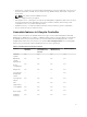
Feature Base Management with IPMI iDRAC Express (Rack and Tower Servers) iDRAC Express (Blade Servers) iDRAC Enterprise Remote services — (through WSMAN) Yes Yes Yes Technical Support Report (TSR) Yes Yes Yes Yes Repurpose or retire system Yes Yes Yes Yes Viewing iDRAC license information After you open the Lifecycle Controller GUI page, you can view details about the iDRAC installed on a server. To view the iDRAC license information: 1. Start Lifecycle Controller.
• The iDRAC Overview and Feature Guide provides information about iDRAC, its licensable features, and license upgrade options. • The Integrated Dell Remote Access Controller (iDRAC) User’s Guide provides information about configuring and using an iDRAC for rack, tower, and blade servers to remotely manage and monitor your system and its shared resources through a network.
– For Client Systems Management documents — dell.com/clientsystemsmanagement – For OpenManage Connections Client Systems Management documents — dell.com/ connectionsclientsystemsmanagement • From the Dell Support site: a. Go to dell.com/support/manuals. b. Under General support section, click Software & Security. c.
2 Using Lifecycle Controller This section provides information about starting, enabling, and disabling Lifecycle Controller. Before using Lifecycle Controller, make sure that the network and iDRAC are configured. For more information, see the integrated Dell Remote Access Controller User’s Guide at dell.com/support/home. Starting Lifecycle Controller To start Lifecycle Controller, restart the system and press during POST to select Lifecycle Controller from the list displayed.
Message Lifecycle Controller Update Required Lifecycle Controller not available Cause Resolution • The embedded device that has Enable Lifecycle Controller. For a backup of the product may more information, see Enabling contain corrupted data. Lifecycle Controller. • Ungracefully exits Lifecycle Controller for 3 consecutive times. Another process is using iDRAC. Enable Lifecycle Controller. For more information, see Enabling Lifecycle Controller.
CAUTION: This action cancels all tasks that are being performed by Lifecycle Controller. It is recommended that you cancel the Lifecycle Controller actions only when absolutely necessary. 1. Press during POST. The System Setup Main Menu page is displayed. 2. In the System Setup Main Menu page, select iDRAC Settings. The iDRAC Settings page is displayed. 3. Select Lifecycle Controller. 4. Under Cancel Lifecycle Controller Actions, select Yes. 5.
• Static IP — Click this option to indicate that the NIC must be configured using a static IP. Type the IP Address Properties — IP Address, Subnet Mask, Default Gateway, DNS Address. If you do not have this information, contact your network administrator. NOTE: The IP Address Source function supports only IPv4. 6. Click Enabled and type the VLAN ID and Priority under Lifecycle Controller VLAN Settings to configure the VLAN settings of a NIC.
Firmware update Firmware rollback Hardware inventory view and export Configure Operating system deployment Platform restore Hardware diagnostics Setting up Lifecycle Controller Using the System Setup and boot manager Import server license Viewing iDRAC license information Restoring a server profile after system board replacement 17
Operating system deployment 3 The OS Deployment feature allows you to deploy standard and custom operating systems on the managed system. You can also configure RAID before installing the operating system if it is not already configured. Lifecycle Controller allows deploying the operating system using the following options: • Manual installation • Unattended installation. For more information on unattended installation, see Unattended installation. • UEFI Secure Boot.
• • Secure Boot — Allows you to enable or disable the Secure Boot option. Click Enabled to secure the boot process by checking if the drivers are signed with an acceptable digital signature. This option is available only for the UEFI boot mode. For more information on Secure Boot, see UEFI Secure Boot. NOTE: The Secure Boot option is available only if the Load Legacy Video Option ROM setting is set to disabled.
Unattended installation Post reboot scenarios Using the optional RAID configuration Using the optional RAID configuration When you install an operating system, you can: • Deploy the operating system without configuring RAID. • Configure the hard-disk drives using the optional RAID configuration wizard and deploy the operating system. Alternatively, you can configure RAID through the RAID configuration page from the Hardware Configuration → Configuration Wizards → RAID Configuration.
NOTE: The unattended installation feature is supported only for Microsoft Windows and Red Hat Enterprise Linux 7 operating systems. If you select an operating system other than Windows or Red Hat Enterprise Linux 7, the Unattended Install option is grayed out.
drivers and copies them to a temporary directory (OEMDRV) on the managed system. These files are deleted after 18 hours or when you: • press to cancel the operating system installation • restart Lifecycle Controller after restarting the server • perform an AC power-cycle operation NOTE: Before installing an operating system, make sure that Lifecycle Controller is updated with the latest driver packs. You can download the latest Lifecycle Controller drivers at dell.com/support.
Monitor 4 Using Lifecycle Controller, you can monitor the hardware inventory and events of a server throughout its life cycle.
NOTE: View and export factory-shipped inventory feature is grayed out if the Repurpose or Retire System option is selected, which permanently deletes the factory-shipped inventory. Related Links Viewing hardware inventory — current or factory shipped Exporting hardware inventory — current or factory shipped Viewing hardware inventory — current or factory shipped NOTE: For factory-shipped inventory, the status of few parameters for the installed components is displayed as Unknown.
5. If you are exporting the inventory to a local USB drive, select USB Drive. If you are exporting the file to a shared folder on a network, select Network Share. For more information, see Exporting Hardware Inventory To A USB Drive or Exporting Hardware Inventory To A Network Share. To verify if Lifecycle Controller is able to connect to the IP address that you entered, click Test Network Connection. By default, Lifecycle Controller pings the Gateway IP, DNS server IP, and the host IP.
• Domain and User Name — Type the domain and user name required to log on to the network share. For example, loginname@myDomain or domain\user name. If there is no domain, type the user name. • Password — Type the correct password. • File Path — Type the sub-directories, if any. For example, 2011\Nov. NOTE: Lifecycle Controller allows 256 characters in a path that includes the file name and file extension.
3. After Lifecycle Controller starts, click Hardware Configuration → View Current Hardware Inventory or Export Current Hardware Inventory to view or export current hardware inventory respectively. If the following message is displayed, click No, reboot the system, and then retry. Hardware change is detected on the system. The current hardware inventory does not contain the latest updates as the hardware inventory update is in progress.
– All — Events related to all categories are listed. – System Health — Events related to the installed hardware such as fan, PSUs, NIC/LOM/CNA link, BIOS errors, and so on. – Storage — Events related to the external or internal storage components such as storage controller, enclosure, HDDs, and software RAID.
NOTE: Lifecycle Controller cannot ping the domain name and cannot display the IP address if the DNS is not able to resolve the domain name. Make sure that the issue with DNS is resolved and retry. 5. Click Finish. The Lifecycle Log is exported to the specified location. Related Links Exporting hardware inventory to a USB drive Exporting hardware inventory to a network share Exporting Lifecycle Log to a USB drive To export the Lifecycle Log to a USB drive: 1.
Adding a work note to the Lifecycle Log You can add a work note to the Lifecycle Log to record comments for your reference. You can enter comments such as scheduled downtime or changes made by administrators who work in different shifts for later reference. NOTE: You can type a maximum of 50 characters in the Lifecycle Log field. The special characters such as <, >, &, and % are not supported. To add a work note: 1. Start Lifecycle Controller. For more information, see Starting Lifecycle Controller. 2.
5 Firmware update Using Lifecycle Controller, the system can be updated using the repositories accessible through FTP or on a locally attached USB drive, DVD, or network share. Use the Firmware Update page to: • • • View the current version of the installed applications and firmwares. View a list of available updates. Select the required updates, downloads (automatic), and then apply the updates to the following components listed in the table.
Updating firmware Firmware update methods The following table lists the various locations or media and methods to perform the updates: NOTE: If the FTP server or network share is used for updates, configure the network card using the Settings wizard before accessing the updates. Table 4.
To update the firmware: 1. Start Lifecycle Controller. For more information, see Starting Lifecycle Controller. 2. In the left pane, click Firmware Update. 3. In the right pane, click Launch Firmware Update. 4. To indicate the repository where the firmware file is stored, select any one of these update repositories: FTP Server, Local Drive(CD or DVD or USB), or Network Share, click Next. The Enter Access Details page is displayed.
NOTE: Make sure that the repository (catalog file) and DUPs are copied to the root folder of the source • Local Drive — Use a USB drive, Dell Server Updates DVD, or Lifecycle Controller OS Driver Packs DVD • Network Share Related Links Comparing firmware versions Using single component DUPs Using a local drive Using a FTP server Using a network share Updating or rolling back devices that affect Trusted Platform Module settings Using a local drive Lifecycle Controller allows you to perform firmware upda
Using a USB drive You can download the repository from the SUU DVD or from an FTP location to a USB drive, and then access the updates from this drive. Before downloading the repository to the USB drive, make sure that the following prerequisites are met: • The updates are downloaded using the Dell Repository Manager and the repository is created on a USB drive. NOTE: To download the complete repository, make sure that the USB drive has 8 GB free space. • Connect the USB drive to the system.
• The updates are downloaded using Dell Repository Manager, and the repository is created on an internal FTP server. To update the system using the Dell FTP server, internal FTP server, or service provider’s FTP server: • Dell FTP Server — In the Address field, enter only ftp.dell.com. • Internal FTP server or service provider’s FTP server — Enter the following details: – User Name — The user name to access the FTP location. – Password — The password to access the FTP location.
NOTE: If the catalog file or DUP is downloaded from ftp.dell.com, do not copy them to a subdirectory. NOTE: Lifecycle Controller allows 256 characters in a path that includes the file name and file extension. For example, if 56 characters are used for file name and extension, only 200 characters can be used for the path. Lifecycle Controller does not support these characters -:, *,?,”,<,>,|,#,%,^, and SPACE.
NOTE: Both 32–bit and 64–bit DUPs are supported. In the File Path or Update package path field, enter the name of the DUP (for example, APP_WIN_RYYYZZZ.EXE) or if the DUP is present in a subdirectory, enter both the subdirectory name and name of the DUP (for example, subdirectory\APP_WIN_RYYYZZZ.EXE). NOTE: Lifecycle Controller allows 256 characters in a path that includes the file name and file extension.
Rolling back to previous firmware versions Rolling back to previous firmware versions You can roll back to earlier versions of a firmware using the Firmware Rollback wizard. NOTE: If you update any firmware only once, the rollback feature provides the option to revert to the factory-installed component firmware image. If you update the firmware more than once, the factory‑installed images are overwritten and you cannot revert to them. To roll back a firmware: 1. Start Lifecycle Controller.
Configure 6 Lifecycle Controller provides various system configuration wizards. Use the configuration wizards to configure system devices. The Configuration Wizards has: • System Configuration Wizards — This wizard includes LCD Panel Security, iDRAC Settings, System Date and Time Configuration, and vFlash SD card Configuration. • Storage Configuration Wizards — This wizard includes RAID Configuration, Key Encryption, and Break Mirror.
6. • Disable Click Finish to apply the changes. Configuring iDRAC To configure iDRAC parameters applicable to the system, such as LAN, common IP settings, IPv4, IPv6, Virtual Media, and LAN user configuration use the iDRAC Settings wizard. NOTE: You can also use the System Setup utility during startup for configuring iDRAC. For more information about the System Setup utility, see Using The System Setup Program And Boot Manager. To configure and manage the iDRAC parameters: 1. Start Lifecycle Controller.
The default system time and system date displayed in Lifecycle Controller is the date and time reported by the system BIOS. 5. Modify the System Time and System Date (HH:MM:SS AM or PM), as required. 6. Click Finish to apply the changes. Configuring vFlash SD card Use the licensed feature to enable or disable the vFlash SD card, check the health and properties, and initialize the vFlash SD card. Lifecycle Controller support vFlash SD cards of sizes 1 GB, 2 GB, 8 GB, 16 GB, and 32 GB.
4. On the System Configuration Wizards page, click vFlash SD Card Configuration. The vFlash SD Card page is displayed. 5. Click Initialize vFlash to delete all the data present in the vFlash SD card. NOTE: The Initialize vFlash option is not available after you disable the vFlash SD card.
configuration if physical disk drives have been moved from one RAID controller to another RAID controller. You have two options: Ignore Foreign Configuration and Clear Foreign Configuration. • If the foreign configuration contains data that you require, click Ignore Foreign Configuration. If you click this option, the disk drive space containing the foreign configuration is not available for use in a new virtual drive.
• RAID 10 — Combines mirrored physical disks with data striping. If a physical disk fails, data can be rebuilt using the mirrored data. RAID 10 offers good read and write performance with good data redundancy. • RAID 50 — A dual-level array that uses multiple RAID 5 sets in a single array. A single physical disk failure can occur in each of the RAID 5 without any loss of data on the entire array.
• Drives remaining for current span — Displays the number of physical disk-drives remaining in the current span based on the span length value selected. • Select the physical disk-drives using the check boxes at the bottom of the screen. The physical diskdrive selection must meet the requirements of the RAID level and span length. To select all the physical disk-drives, click Select All. After you select the option, the option changes to Deselect.
Viewing summary The Summary page displays the virtual disk attributes based on selections. CAUTION: Clicking Finish deletes all existing virtual drives except any foreign configurations that you specified. All data residing on the virtual drives is lost. To return to a previous page to review or change selections, click Back. To close the wizard without making changes, click Cancel. Click Finish to create a virtual drive with the displayed attributes.
9. To apply the RAID configuration, click Finish. Related Links Selecting a RAID controller Foreign configuration found Selecting RAID levels Selecting physical disks Setting virtual disk attributes Viewing summary Creating a secure virtual disk on a RAID controller Make sure that the controller is encrypted with a local key. For more information on encrypting with a local key, see Key Encryption. To create a secure virtual disk on a RAID controller: 1. Start Lifecycle Controller.
Key encryption Use the Key Encryption feature to: • Apply local encryption for PERC H710, H710P, H730, H730P, H810, and H830 RAID controllers. • Delete the local encryption key. • Encrypt the existing unsecure virtual drives. • To change an existing encryption key to another one. NOTE: For more information about the key encryption feature, see the Key Encryption in Lifecycle Controller white paper at delltechcenter.com/lc.
• Remove encryption and delete data — Delete the encryption key on the controller and all the secure virtual drives along with its data. After deletion, controller state changes to No encryption mode. Related Links Encrypting unsecure virtual disks Rekey controller with new local key Removing encryption and deleting data Encrypting unsecure virtual disks Make sure that the following prerequisites are met: • Selected controller is security-capable.
Removing encryption and deleting data To remove the encryption and delete the data on the virtual disks: CAUTION: The existing encryption, virtual drives, and all the data are permanently deleted. 1. Start Lifecycle Controller. For more information, see Starting Lifecycle Controller. 2. In the left pane, click Hardware Configuration. 3. In the right pane, click Configuration Wizards and click Key Encryption. 4. Select the controller on which you must remove the key that was applied and click Next.
NOTE: You can also use System Setup utility during startup to configure the following devices. For more information about the System Setup utility, see Using The System Setup Program And Boot Manager. • System BIOS Settings • iDRAC Device Settings • NICs NOTE: You can configure only one NIC at a time.
* QLogic QLE2660 Single Port FC16 HBA (LP) * QLogic QLE2662 Dual Port FC16 HBA * QLogic QLE2662 Dual Port FC16 HBA (LP) * QLogic QME2662 Dual Port FC16 HBA Mezzanine * QLogic QLE2560 FC8 Single Channel HBA * QLogic QLE2562 FC8 Dual Channel HBA * QLogic FC8 Embedded Mezz Card QME2572 * Emulex LPe16000 Single Port FC16 HBA * Emulex LPe16000 Single Port FC16 HBA (LP) * Emulex LPe16002 Dual Port FC16 HBA * Emulex LPe16002 Dual Port FC16 HBA (LP) * Emulex LPm16002 Dual Port FC16 HBA Mezzan
• Enabled with iSCSI to use the NIC to boot from an iSCSI target. Modifying device settings To modify device settings using the Advanced Hardware Configuration: NOTE: You can also modify the device settings by using the System Setup utility during startup. For more information about the System Setup utility, see Using The System Setup Program And Boot Manager. 1. Start Lifecycle Controller. For more information, see Starting Lifecycle Controller. 2. In the left pane, select System Setup. 3.
FTP authentication Although you must provide the user name and password for the FTP server, Lifecycle Controller supports anonymous login to the FTP server using the FTP server address to download the catalog information. If you use a firewall, you should configure it to allow outgoing FTP traffic on port 21. The firewall must be configured to accept incoming FTP response traffic. Requirements for a local FTP server The following requirements apply when configuring a local FTP server.
– Address — The IP address of the local FTP server or ftp.dell.com – User Name — The user name to access the FTP location. – Password — The password to access this FTP location. – Proxy Server — The server host name or the IP address of the proxy server. – Proxy Port — The port number of the proxy server. – Proxy Type — The type of proxy server. HTTP and SOCKS 4 proxy server types are supported by Lifecycle Controller. – Proxy User Name — The user name required to access the proxy server.
Maintain 7 Using Lifecycle Controller, you can maintain the health of a system throughout its life cycle using the features such as Part Replacement Configuration and Platform Restore. Platform restore Lifecycle Controller allows you to create a copy (image file) of the server's profile on the vFlash SD card installed on the server.
– User name and password for RAID controller and BIOS. – Component certificates. – Licenses. – Signature to validate that the backup file is not tampered and generated by Lifecycle Controller. The server profile backup image file does not contain: • Operating system or any data stored on hard-disk drives or virtual drives. • vFlash SD card partition information. • Lifecycle log. • Dell diagnostics. • Dell OS Driver Pack.
Component Firmware Configuration Security Information* Lifecycle Controller Yes NA NA Backplane NA NA NA CPLD NA NA NA Power Supply Unit Yes NA NA FC HBA Yes Yes NA Enclosure NA NA NA PCIe SSD Yes NA NA * The security information refers to the user credentials that are used to access the components.
Alternatively, to generate an encrypted backup file using a passphrase, enter the passphrase and click Finish. In the absence of a passphrase, Lifecycle Controller encrypts the backup image file with a default passphrase (internally generated). 5. In the Backup File Passphrase field, enter a passphrase. For example, Rt@#12tv. NOTE: A valid passphrase contains 8–32 characters. It must include a combination of uppercase and lowercase letters, numbers, symbols, and must not have white spaces.
To export the server profile to a USB drive or a network share: 1. Start Lifecycle Controller. For more information, see Starting Lifecycle Controller. 2. In the left pane, select Platform Restore. 3. In the right pane, select Export Server Profile. 4. Select either USB Drive or Network Share, enter the details, and then click Finish. NOTE: You can also use a USB drive that is attached to the client system while operating remotely. To use the USB drive remotely, use the Virtual Media feature.
• The Service Tag of the server is same as when the backup was taken. • If you are restoring from a vFlash SD card, the vFlash SD card must be installed and must contain the backup image in a folder labeled SRVCNF. This image must be from the same server that you are trying to restore. • If you are restoring from a network share, make sure that the network share where the backup image file is stored is accessible. You can import the server profile from a vFlash SD card, Network Share, or a USB drive.
8. If you have secured the backup image file with a passphrase, enter the passphrase (entered during backup) in the Backup File Passphrase field, and then click Finish. Related Links System or feature behavior during import Import server profile Importing server profile after system board replacement Importing server profile from a USB drive To import from a USB drive: 1. Start Lifecycle Controller. For more information, see Starting Lifecycle Controller. 2. In the left pane, select Platform Restore.
2. System turns on and boots to System Services to execute tasks to perform firmware restore for supported devices (BIOS, storage controllers, and Add-in NIC cards). 3. System reboots and goes to System Services to execute tasks for firmware validation, configuration restore for supported devices (BIOS, storage controllers, and Add-in NIC cards) and the final verification of all tasks executed. 4. System turns off and performs iDRAC configuration and firmware restore.
NOTE: To import a server profile, you must have an Enterprise license and administratorlevel rights. • To manually enter a Service Tag, click Manually configure service tag. On the Service Tag Settings page, type the Service Tag, and then click OK. Import server license Use the Import Server License feature to import an iDRAC license from the Lifecycle Controller GUI.
Importing an iDRAC license from a USB drive To import a server license from a USB drive: 1. Start Lifecycle Controller. For more information, see Starting Lifecycle Controller. 2. In the left pane, click Platform Restore. 3. In the right pane, click Import Server License. 4. On the Import Server License page, click USB Drive. NOTE: If a USB Drive is not connected, the following message is displayed: Insert Media 5. From the Select Device drop-down menu, select the attached USB drive. 6.
The Part Replacement Configuration page is displayed. 4. From the part firmware update drop-down menu, select one of the following: • Disabled — Firmware update on replaced parts is not performed. • Allow version upgrade only — Firmware update on replaced parts is performed only if the firmware version of the new part is earlier than the existing part. • Match firmware of replaced part — Firmware on the new part is updated to the version of the original part.
• Reuse a managed system for a different application. Deleting server information 1. Start Lifecycle Controller. For more information, see Starting Lifecycle Controller. 2. In the left pane, click Hardware Configuration, and then click Repurpose or Retire System. 3. On the Select Components page, select the features and components to delete from Server Features and Storage Components. 4. Click Next. A summary of the features and components selected for deletion is displayed. 5.
Lifecycle Controller allows you to collect data from the following options: • Hardware • Software controller logs • OS and Software application data NOTE: OS and Software application data is enabled only if this data is already collected and cached using the OS collector tool on iDRAC. Lifecycle Controller displays this option along with the time stamp of data collection. You can select this option to retrieve the cached data available on the server.
4. Click Next. Lifecycle Controller checks the availability of hardware, operating system and application data, and RAID controller logs, and then displays the options listed in step 5. If the operating system and application data, or RAID controller logs are unavailable, the relevant options are grayed out. The duration to collect the selected data is displayed next to the options listed in step 5. 5.
Troubleshooting and frequently asked questions 8 This section describes the error messages commonly generated by Lifecycle Controller and provides suggestions for resolving the issues. This section also lists the questions that are frequently asked by Lifecycle Controller users. Error messages Each error message that is generated from Lifecycle Controller has a Message ID, Message Description, and Recommended Response Action in a single dialog box.
No, Lifecycle Controller only provides drivers that are required for operating system installation. To update the drivers used by an installed operating system, see your operating system’s Help documentation. 8. Can I add my own drivers and firmware for updating Lifecycle Controller to a local USB drive? No, only drivers and firmware downloaded from the Dell Server Updates DVD are supported. For more information, see Configuring Local USB Drive. 9. Can I delete Lifecycle Controller? No. 10.
18. What should I do if I have an issue with mouse cursor synchronization when I access Lifecycle Controller through the iDRAC Virtual Console? Make sure that the Single Cursor option under Tools menu is selected on the iDRAC Virtual Console client. For more information, see the Integrated Dell Remote Access Controller (iDRAC) User’s Guide at dell.com/support/home. 19.
Easy-to-use system component names 9 The following table lists the Fully Qualified Device Descriptor (FQDD) of the system components and the equivalent easy-to-use names. Table 8. Easy-to-use Names of System Components FQDD of System Component Name Easy-to-use Name RAID.Integrated.1-1 Integrated RAID Controller 1 RAID.Slot.1-1 RAID Controller in Slot 1 NIC.Mezzanine.1B-1 NIC in Mezzanine NIC.Mezzanine.1C-1 NIC.Mezzanine.1C-2 NIC.Mezzanine.3C-2 NonRAID.Integrated.
FQDD of System Component Name Easy-to-use Name P2PBridge.Mezzanine.2B-1 Embedded Host Bridge in Mezzanine 1 (Fabric B) USBUHCI.Embedded.1-1 Embedded USB UHCI 1 USBOHCI.Embedded.1-1 Embedded USB OHCI 1 USBEHCI.Embedded.1-1 Embedded USB EHCI 1 Disk.SATAEmbedded.A-1 Disk on Embedded SATA Port A Optical.SATAEmbedded.B-1 Optical Drive on Embedded SATA Port B TBU.SATAExternal.C-1 Tape Back-up on External SATA Port C Disk.USBFront.1-1 Disk connected to front USB 1 Floppy.USBBack.
FQDD of System Component Name Easy-to-use Name Fan.Slot. 1 Fan 1 Fan.Slot. 2 Fan 2 … … Fan.Slot. 9 Fan 9 MC.Chassis.1 Chassis Management Controller 1 MC.Chassis.2 Chassis Management Controller 2 KVM.Chassis.1 KVM IOM.Slot.1 IO Module 1 … … IOM.Slot.6 IO Module 6 PSU.Slot.1 Power Supply 1 … ... PSU.Slot.6 Power Supply 6 CPU.Socket.1 CPU 1 System.Modular.2 Blade 2 DIMM.Socket.
Using the System Setup and boot manager 10 System Setup enables you to manage your system hardware and specify BIOS-level options. The following keystrokes provide access to system features during startup: Table 9. System setup keystrokes Keystroke Description Opens the System Setup page.
Choosing the system boot mode System Setup enables you to specify the boot mode for installing your operating system: • BIOS boot mode (the default) is the standard BIOS-level boot interface. • UEFI boot mode is an enhanced 64-bit boot interface based on Unified Extensible Firmware Interface (UEFI) specifications that overlays the system BIOS. You must select the boot mode in the Boot Mode field of the Boot Settings screen of System Setup.
NOTE: For the standard graphics browser only. Moves to the previous page till you view the main screen. Pressing in the main screen displays a message that prompts you to save any unsaved changes and restarts the system. Displays the System Setup help file. NOTE: For most of the options, any changes that you make are recorded but do not take effect until you restart the system.
Menu Item Description System Profile Settings Displays options to change the processor power management settings, memory frequency, and so on. System Security Displays options to configure the system security settings like, system password, setup password, TPM security, and so on. It also enables or disables support for local BIOS update, the power and NMI buttons on the system. Miscellaneous Settings Displays options to change the system date, time, and so on.
Menu Item Description and Dell Fault Resilient Mode. By default, the Memory Operating Mode option is set to Optimizer Mode. NOTE: The Memory Operating Mode can have different defaults and available options based on the memory configuration of your system. NOTE: The Dell Fault Resilient Mode establishes an area of memory that is fault resilient.
Menu Item Description DCU IP Prefetcher Allows you to enable or disable the Data Cache Unit (DCU) IP prefetcher. By default, the DCU IP Prefetcher option is set to Enabled. Execute Disable Allows you enable or disable execute disable memory protection technology. By default, the Execute Disable option is set to Enabled. Logical Processor Idling Allows you to enable or disable the OS capability to put logical processors in the idling state in order to reduce power consumption.
Menu Item Description Port E Auto enables BIOS support for the device attached to SATA port E. By default, Port E is set to Auto. Port F Auto enables BIOS support for the device attached to SATA port F. By default, Port F is set to Auto. NOTE: Ports A, B, C, and D are used for the backplane drives, port E for the optical drive (CD/DVD), and port F for the tape drive. Boot settings screen Menu Item Description Boot Mode Allows you to set the boot mode of the system.
Menu Item Description Internal USB Port Allows you to enable or disable the internal USB port. By default, the Internal USB Port option is set to On. Internal SD Card Port Enables or disables the system’s internal SD card port. By default, the Internal SD Card Port option is set to On. NOTE: This option is displayed only if IDSDM is installed on the system board. Internal SD Card Redundancy If set to Mirror mode, data is written on both SD cards.
Menu Item Description NOTE: Only Serial Device 2 can be used for Serial Over LAN (SOL). To use console redirection by SOL, configure the same port address for console redirection and the serial device. External Serial Connector Allows you to associate the external serial connector to serial device 1, serial device 2, or remote access device. By default, the External Serial Connector option is set to Serial Device1. NOTE: Only Serial Device 2 can be used for SOL.
Menu Item Description Monitor/Mwait Allows you to enable Monitor/Mwait instructions in the processor. By default, the Monitor/Mwait option is set to Enabled for all system profiles, except Custom. NOTE: This option can be disabled only if the C States option in Custom mode is disabled. NOTE: When C States is enabled in Custom mode, changing the Monitor/ Mwait setting does not impact system power/performance. Memory Patrol Scrub Allows you to set the memory patrol scrub frequency.
Menu Item Description Intel TXT Allows you to enable or disable Intel Trusted Execution Technology (TXT). To enable Intel TXT, Virtualization Technology must be enabled and TPM Security must be Enabled with Pre-boot measurements. By default, the Intel TXT option is set to Off. BIOS Update Control Allows you to update the BIOS using either DOS or UEFI shell-based flash utilities. For environments that do not require local BIOS updates, it is recommended to set this option to Disabled.
System and setup password features You can create a system password and a setup password to secure your system. To enable creation of the system and setup password, the password jumper must be set to enabled. For more information on the password jumper settings, see System Board Jumper Settings. System password This is the password that you must enter before you can boot your system.
8. Re-enter the setup password that you entered earlier and click OK. 9. Press to return to the System BIOS screen. Press again, and a message prompts you to save the changes. NOTE: Password protection does not take effect until the system reboots. Deleting or changing an existing system and/or setup password Ensure that the Password jumper is set to enabled and the Password Status is Unlocked before attempting to delete or change the existing System and/or Setup password.
Operating with a setup password enabled If Setup Password is Enabled, enter the correct setup password before modifying most of the System Setup options. If you do not enter the correct password in three attempts, the system displays the message Invalid Password! Number of unsuccessful password attempts: System Halted! Must power down. Even after you shut down and restart the system, the error message is displayed until the correct password is entered.
Key Description NOTE: For the standard graphics browser only. Moves to the previous page till you view the main screen. Pressing in the main screen exits the Boot Manager and proceeds with system boot. Displays the System Setup help file. NOTE: For most of the options, any changes that you make are recorded but do not take effect until you restart the system.
Embedded system management The Dell Lifecycle Controller provides advanced embedded systems management throughout the server’s lifecycle. The Lifecycle Controller can be started during the boot sequence and can function independently of the operating system. NOTE: Certain platform configurations may not support the full set of features provided by the Lifecycle Controller.