Dell Lifecycle Controller GUI v2.40.40.40 User's Guide October 2016 Rev.
Notes, cautions, and warnings NOTE: A NOTE indicates important information that helps you make better use of your product. CAUTION: A CAUTION indicates either potential damage to hardware or loss of data and tells you how to avoid the problem. WARNING: A WARNING indicates a potential for property damage, personal injury, or death. © 2016 Dell Inc. All rights reserved. This product is protected by U.S. and international copyright and intellectual property laws.
Contents Chapter 1: Introduction................................................................................................................. 7 Why use Lifecycle Controller?..........................................................................................................................................7 Benefits of using iDRAC with Lifecycle Controller...................................................................................................... 7 What's new in this release?..............
Lifecycle Controller log.................................................................................................................................................... 29 Viewing Lifecycle Log history...................................................................................................................................29 Exporting Lifecycle Log.............................................................................................................................................
Configuring a local USB drive.........................................................................................................................................56 Copying repository to a local USB drive from the Dell Server Updates DVD............................................... 57 Using Dell Repository Manager to create the repository and copy to a USB drive.................................... 57 Configuring NFS and CIFS servers......................................................................
System Profile Settings screen................................................................................................................................82 System security screen..............................................................................................................................................82 Miscellaneous settings...............................................................................................................................................
1 Introduction Dell Lifecycle Controller provides advanced embedded systems management to perform systems management tasks such as deploy, configure, update, maintain, and diagnose using a graphical user interface (GUI). It is delivered as part of integrated Dell Remote Access Controller (iDRAC) out-of-band solution and embedded Unified Extensible Firmware Interface (UEFI) applications in the latest Dell servers.
● Secure environment — By providing secure access to remote servers, administrators can perform critical management functions while maintaining server and network security. ● Enhanced embedded management — Lifecycle Controller provides deployment and simplified serviceability through the LC GUI for local deployment, Remote Services (wsman) interfaces for remote deployment integrated with Dell OpenManage Essentials and partner consoles, and Redfish UI.
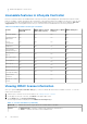
Feature matrix The following table lists the Lifecycle Controller features supported on the 12 th and 13 th generation Dell PowerEdge servers. Table 1.
● Enhanced repurpose or retire server Licensable features in Lifecycle Controller Lifecycle Controller features are available based on the type of license (Basic Management with IPMI, iDRAC Express, iDRAC Express for Blades, or iDRAC Enterprise) that you purchase. Only licensed features are available in the Lifecycle Controller GUI. For more information about managing licenses, see the Integrated Dell Remote Access Controller User's Guide at dell.com/ support/home.
Table 3. : License Information ● Description — Indicates the license details. ● License Type — Indicates the type of license of the device. For example, Evaluation, Evaluation Extension, or Perpetual. ● Expiration — Indicates the date and time at which the license expires. Other documents you may need In addition to this guide, you can access the following guides available at dell.com/support/home.
Accessing support content from the Dell EMC support site Access supporting content related to an array of systems management tools using direct links, going to the Dell EMC support site, or using a search engine. ● Direct links: ○ For Dell EMC Enterprise Systems Management and Dell EMC Remote Enterprise Systems Management—https:// www.dell.com/esmmanuals ○ For Dell EMC Virtualization Solutions—https://www.dell.com/SoftwareManuals ○ For Dell EMC OpenManage—https://www.dell.
2 Using Lifecycle Controller This section provides information about starting, enabling, and disabling Lifecycle Controller. Before using Lifecycle Controller, make sure that the network and iDRAC are configured. For more information, see the Integrated Dell Remote Access Controller User’s Guide at dell.com/esmmanuals.
Table 4. Start messages during POST, cause, and resolution Message Cause Resolution ○ 3 consecutive unsuccessful attempts to enter Lifecycle Controller GUI. ○ 3 consecutive unsuccessful attempts to complete inventory collection. ○ 3 consecutive unsuccessful attempts to perform tasks in Automated Task applications. Lifecycle Controller not available Another process is using iDRAC. Wait for 30 minutes for the current process to complete, restart the system, and then retry.
The System Setup Main Menu page is displayed. 2. In the System Setup Main Menu page, select iDRAC Settings. The iDRAC Settings page is displayed. 3. Select Lifecycle Controller. 4. Under Cancel Lifecycle Controller Actions, select Yes. 5. On the System Setup Main Menu page, select Finish to save the settings. 6. Select Yes to restart the system. Using Lifecycle Controller for the first time After you start Lifecycle Controller for the first time, by default the Initial Setup Wizard page is launched.
● No Configuration — indicates that the NIC must not be configured. ● DHCP — indicates that the NIC must be configured using an IP address from a DHCP server. If DHCP is selected, a DHCP IP address is displayed on the Network Settings page. ● Static IP — indicates that the NIC must be configured using a static IP. Type the IP Address Properties — IP Address, Subnet Mask, Default Gateway, and DNS Address. If you do not have this information, contact your network administrator. 6.
NOTE: For recommended characters while accessing network shares, see Recommended characters while accessing network shares on page 17. Table 5. Recommended characters for user names Characters Length 0-9 1-16 A-Z a-z -!#$%&()*/;?@[\]^_`{|}~+<=> Table 6. Recommended characters for passwords Characters Length 0-9 1-20 A-Z a-z '-!"#$%&()*,./:;?@[\]^_`{|}~+<=> NOTE: You may be able to create user names and passwords that include other characters.
Setting up Lifecycle Controller from the home page If you miss to make any changes in the Initial Setup Wizard, or if you want to make any configuration changes later, restart the server, press F10 to launch Lifecycle Controller, and select Settings from the home page. Specifying language and keyboard type 1. Start Lifecycle Controller. For more information, see Starting Lifecycle Controller. 2. On the left pane, click Settings. 3. On the Settings pane, click Language and Keyboard.
NOTE: If Lifecycle Controller settings are not correctly configured, an error message is displayed. NOTE: If you are unable to connect to a network, verify the settings. For information about correct network settings, contact your network administrator. Lifecycle Controller features This section provides a brief description about the Lifecycle Controller features and helps you understand how to use the Lifecycle Controller wizards most effectively.
3 Operating system deployment The OS Deployment feature allows you to deploy standard and custom operating systems on the managed system. You can also configure RAID before installing the operating system if it is not already configured. Lifecycle Controller allows deploying the operating system using the following options: ● Manual installation ● Unattended installation. For more information on unattended installation, see Unattended installation. ● UEFI Secure Boot.
● Secure Boot — Allows you to enable or disable the Secure Boot option. Click Enabled to secure the boot process by checking if the drivers are signed with an acceptable digital signature. This option is available only for the UEFI boot mode. For more information on Secure Boot, see UEFI Secure Boot. NOTE: The Secure Boot option is available only if the Load Legacy Video Option ROM setting is set to disabled.
● Configure the hard-disk drives using the optional RAID configuration wizard and deploy the operating system. Alternatively, you can configure RAID through the RAID configuration page from the Hardware Configuration > Configuration Wizards > RAID Configuration. Configuring RAID using the operating system deployment wizard To configure RAID using the OS Deployment page: NOTE: If the system has a RAID controller, you can configure a virtual disk as the boot device.
There are two BIOS attributes that are associated with Secure Boot: ● Secure Boot — Displays if the Secure Boot is enabled or disabled. ● Secure Boot Policy — Allows you to specify the policy or digital signature that BIOS uses to authenticate. The policy can be classified as: ○ Standard — BIOS uses the default set of certificates to validate the drivers and operating system loaders during the boot process.
Table 8. Post reboot scenarios Scenario User Action and Impact NOTE: If you press during the installation process or a restart, the drivers provided by the operating system deployment wizard are removed. During the 18-hour period when drivers are extracted Lifecycle Controller does not allow DUP after the operating system to a temporary location after the operating system is installation.
4 Monitor Using Lifecycle Controller, you can monitor the hardware inventory and events of a server throughout its life cycle.
NOTE: View and export factory-shipped inventory feature is grayed out if the Repurpose or Retire System option is selected, which permanently deletes the factory-shipped inventory. Related tasks Viewing hardware inventory — current or factory shipped on page 26 Exporting hardware inventory — current or factory shipped on page 26 Viewing hardware inventory — current or factory shipped NOTE: For factory-shipped inventory, the status of few parameters for the installed components is displayed as Unknown.
NOTE: If the domain name is not resolved in the DNS, then you cannot use Lifecycle Controller to ping the domain name and view the IP address. Make sure that the DNS issue is resolved, and then retry. 6. Click Finish to export the inventory. The HardwareInventory __.xml or FactoryShippedHWInventory_.xml file is copied to the specified location. For the current inventory, the time stamp is in the format yyyy-mm-ddthh:mm:ss, where ‘t’ indicates time.
NOTE: Lifecycle Controller allows 256 characters in a path that includes the file name and file extension. For example, if 56 characters are used for file name and extension, only 200 characters can be used for the path. Lifecycle Controller does not support these characters -:, *,?,”,<,>,|,#,%,^, and SPACE. NFS For NFS, type the following details: ● Share Name — Type the server IP or hostname followed by the root of the network share. Examples: \ \192.168.0.120\sharename or \\hostname\sharename ● File Pat
export the latest hardware inventory, relaunch Lifecycle Controller and retry. Do you want to continue with the old current hardware inventory information? Related tasks Viewing hardware inventory — current or factory shipped on page 26 Exporting hardware inventory — current or factory shipped on page 26 Lifecycle Controller log Lifecycle Controller Log provides a record of past activities on a managed system.
● ● ● ● NOTE: These options are available in the Filter by Category drop-down menu. Select the category to filter the data depending on the category option selected. Severity ○ Critical — Indicates the events that are business-critical. ○ Informational — Indicates the events that are generated only for information purpose. Message ID — Each event is represented with a unique Message ID. For example, SWC0001. Description — A brief description about the event. For example, Dell OS Drivers Pack, v.6.4.0.
NOTE: Lifecycle Controller allows 256 characters in a path that includes the file name and file extension. For example, if 56 characters are used for file name and extension, only 200 characters can be used for the path. Lifecycle Controller does not support these characters -:, *,?,",<,>,|,#,%,^, and SPACE. Exporting Lifecycle Log to a network share To export to a network share, select CIFS or NFS and type the required details.
5 Firmware update Using Lifecycle Controller, the system can be updated using the repositories accessible through FTP or on a locally attached USB drive, DVD, or network share. Use the Firmware Update page to: ● View the current version of the installed applications and firmware. ● View a list of available updates. ● Select the required updates, downloads (automatic), and then apply the updates to the following components listed in the table.
Version compatibility on page 34 Related tasks Updating firmware on page 34 Topics: • • • • Firmware update methods Version compatibility Updating firmware Firmware rollback Firmware update methods The following table lists the various locations or media and methods to perform the updates: NOTE: If the FTP server or network share is used for updates, configure the network card using the Settings wizard before accessing the updates. Table 10.
Version compatibility The version compatibility feature enables you to update the component firmware versions that are compatible with system components. In case of compatibility issues, Lifecycle Controller displays upgrade or downgrade error messages during the update. Updating firmware You can update to the latest version of Lifecycle Controller using the Firmware Update wizard. It is recommended that you run the Firmware Update wizard regularly to access the latest updates.
NOTE: When applying more than one update, the system may restart between updates. In this case, Lifecycle Controller restarts the server and automatically continues the update process. NOTE: iDRAC resets while updating iDRAC. If the iDRAC firmware update is interrupted for any reason, wait for up to 30 minutes before you attempt another firmware update.
To access the repository on the local drive, create a repository on a DVD or USB drive and attach it to the server locally or using a virtual media. Using a DVD Use either the Server Update Utility (SUU) DVDs or custom DVDs (SUU ISO downloaded from dell.com/support and written to a DVD) to perform the firmware updates. The available DVDs are: ● OpenManage SUU DVD to update all the server components such as Lifecycle Controller, Dell Diagnostics, BIOS, RAID controller, NIC, iDRAC, and Power Supply Unit.
● Using Non-Proxy FTP Server ● Using Proxy FTP Server Related concepts Accessing updates on a local FTP server on page 56 Configuring a local USB drive on page 56 Using a non-proxy FTP server Lifecycle Controller can access the latest firmware from ftp.dell.com. It downloads the DUPs from this location to perform firmware update. Before performing an update using a non-proxy FTP server, make sure that the following prerequisites are met: ● The network settings are configured (Settings > Network Settings).
NOTE: If the catalog file or DUP is downloaded from ftp.dell.com, do not copy them to a subdirectory. NOTE: Lifecycle Controller allows 256 characters in a path that includes the file name and file extension. For example, if 56 characters are used for file name and extension, only 200 characters can be used for the path. Lifecycle Controller does not support these characters -:, *,?,”,<,>,|,#,%,^, and SPACE.
NOTE: HTTP, SOCKS 4, and SOCKS 5 (for IPv6) proxy server types are supported in this release. HTTPS is not supported in LC-UI. Using single component DUPs To use single component Dell Update Packages (DUP), download the Dell Update Package (only .exe) from the Dell FTP site (ftp.dell.com), or copy from the Server Update Utility DVD, or from dell.com/support to a local hard disk drive or network share. NOTE: Make sure that the file name for the single component DUPs does not have any blank space.
● Every time a firmware image is updated, the earlier version of the firmware image is backed up. ● Every time a rollback operation is performed, the previously installed firmware becomes the current version. However, for iDRAC, the previously installed version becomes the current version and the current version is stored as the previous version.
You can choose not to update or roll back those components by navigating to the Select Updates page, and then clearing the options for the appropriate components.
6 Configure Lifecycle Controller provides various system configuration wizards. Use the configuration wizards to configure system devices. The Configuration Wizards has: ● System Configuration Wizards — This wizard includes LCD Panel Security, iDRAC Settings, System Date and Time Configuration, and vFlash SD card Configuration. ● Storage Configuration Wizards — This wizard includes RAID Configuration, Key Encryption, and Break Mirror.
Controlling access to the front panel To control access to the front panel: 1. Start Lifecycle Controller. For more information, see Starting Lifecycle Controller. 2. From the Lifecycle Controller Home page, select Hardware Configuration. 3. In the right pane, select Configuration Wizards. 4. On the System Configuration Wizards page, click LCD Panel Security. 5. Set System Control Panel Access to one of the following options: ● View and Modify ● View Only ● Disable 6. Click Finish to apply the changes.
3. In the right pane, select Configuration Wizards. 4. Under System Configuration Wizards, click System Time and Date Configuration. The default system time and system date displayed in Lifecycle Controller is the date and time reported by the system BIOS. 5. Modify the System Time and System Date (HH:MM:SS AM or PM), as required. 6. Click Finish to apply the changes.
Configuring RAID If your system has one or more supported PERC RAID controllers with PERC 8 firmware or later, or software RAID controllers, use the RAID Configuration wizard to configure a virtual disk as the boot device. NOTE: Create boot virtual disk only from disk drive populated across slots 0–3 of the system. For slot information, see the server Owner’s Manual at dell.com/poweredgemanuals.
Viewing current RAID configuration The View Current RAID Configuration and Select Controller page displays the attributes of any virtual disks already configured on the supported RAID controllers attached to the system. You have two options: ● Accept the existing virtual disks without changing. To select this option, click Back. If you have to install the operating system on an existing virtual disk, make sure that the virtual disk size and RAID level are correct.
Table 12. RAID level and number of disks RAID Level Minimum Number of Disks 6 4 10 4 50 6 60 8 * For PERC S110 and S130 RAID controllers, a minimum of two hard-disk drives are required. Selecting physical disks Use the Select Physical Disks screen to select the physical disks to be used for the virtual drive and select the physical disk drive-related properties. The number of physical disks required for the virtual disk varies depending on the RAID level.
● ● ● ● ● ○ Read Ahead — The controller reads sequential sectors of the virtual drives when seeking data. The Read Ahead policy may improve system performance if the data is written to sequential sectors of the virtual drives. ○ No Read Ahead — The controller does not use the Read Ahead policy. The No Read Ahead policy may improve system performance, if the data is random and not written to sequential sectors.
NOTE: From Lifecycle Controller UI, you can deploy only Windows server operating system using software RAID controller. To configure software RAID: 1. Start Lifecycle Controller. For more information, see Starting Lifecycle Controller. 2. In the left pane, click Hardware Configuration. 3. In the right pane, click Configuration Wizards. 4. Under Storage Configuration Wizards, click RAID Configuration to launch the wizard. The View Current RAID Configuration and Select Controller page is displayed. 5.
10. To apply the RAID configuration, click Finish. Related concepts Selecting a RAID controller on page 46 Foreign configuration found on page 45 Selecting RAID levels on page 46 Selecting physical disks on page 47 Setting virtual disk attributes on page 47 Viewing summary on page 48 Related tasks Applying the local key on a RAID controller on page 50 Key encryption Use the Key Encryption feature to: ● ● ● ● Apply local encryption for PERC H710, H710P, H730, H730P, H810, and H830 RAID controllers.
● Encrypt unsecure virtual disks — Enable data encryption on all the security-capable, unsecure virtual drives. NOTE: This option is available if there are secure-capable virtual disks connected to a security-capable controller. ● Rekey controller and encrypted disks with a new key — Replace the existing local key with a new key. ● Remove encryption and delete data — Delete the encryption key on the controller and all the secure virtual drives along with its data.
Removing encryption and deleting data To remove the encryption and delete the data on the virtual disks: CAUTION: The existing encryption, virtual drives, and all the data are permanently deleted. 1. Start Lifecycle Controller. For more information, see Starting Lifecycle Controller. 2. In the left pane, click Hardware Configuration. 3. In the right pane, click Configuration Wizards and click Key Encryption. 4. Select the controller on which you must remove the key that was applied and click Next. 5.
○ ○ ○ ○ ○ ○ ○ ○ ○ ○ ○ ○ ○ ○ ○ ○ ○ ○ ○ ○ ○ ○ ○ ○ ○ ○ ○ ○ ○ ○ ○ ○ ○ ○ ○ ○ ○ ○ ○ ○ ○ ○ ○ ○ ○ ○ ○ ○ BCM5709C Dual Port Rack Mezzanine Card BCM5709S Dual Port SERDES Mezzanine Card for Blade Systems BCM57710 10GBase-T Single Port NIC BCM57710 10GBase-T Dual Port Rack Mezzanine Card BCM57710 Dual Port KX4 Blade Mezzanine Card BCM57711 Dual Port KX4 Noble MC BCM95708C PCI-E NIC BCM95709C 10/100/1000BASET Quad Port NIC BCM95709 iSCSI Offload Dual Port NIC BCM957711 10G SFP+ Dual Port NIC Broadcom 57810S DP 10G SFP
■ ■ ■ ■ ■ ■ ■ ■ ■ ■ ■ ■ QLogic QLE2660 Single Port FC16 HBA (LP) QLogic QLE2662 Dual Port FC16 HBA QLogic QLE2662 Dual Port FC16 HBA (LP) QLogic QME2662 Dual Port FC16 HBA Mezzanine QLogic QLE2560 FC8 Single Channel HBA QLogic QLE2562 FC8 Dual Channel HBA QLogic FC8 Embedded Mezz Card QME2572 Emulex LPe16000 Single Port FC16 HBA Emulex LPe16000 Single Port FC16 HBA (LP) Emulex LPe16002 Dual Port FC16 HBA Emulex LPe16002 Dual Port FC16 HBA (LP) Emulex LPm16002 Dual Port FC16 HBA Mezzanine RAID ● ● ● ● ● ●
Based on the configuration setting changes, the following message may be displayed: One or more of the settings requires a reboot to be saved and activated. Do you want to reboot now? 5. Select No to continue making additional configuration changes or select Yes to save the changes and exit the wizard. All changes are applied during the next system restart.
3. Use this local FTP server for firmware update. Using Dell Repository Manager to create the repository and copy it to a local FTP server To create and copy the repository: 1. Copy the repository created using the Dell Repository Manager to the root directory of the local FTP server. NOTE: For information about creating a repository for your system, see the Dell Repository Manager User’s Guide at dell.com/support/home. 2. Use this local FTP server for firmware update.
Copying repository to a local USB drive from the Dell Server Updates DVD To copy a repository: 1. Download the latest Dell Server Updates ISO image file from dell.com/support. 2. Copy the repository folder of the DVD to the root directory of the USB drive. 3. Use this USB drive for firmware update. Using Dell Repository Manager to create the repository and copy to a USB drive To create and copy the repository: 1.
Disabling the Digitally sign communications option To disable the Digitally sign communications (always) option, perform the following tasks: 1. Open Control Panel and select Administrative Tools. 2. Click Local Security Policy. 3. On the left navigation pane, expand the Local Policies option and select Security Options. 4. Double-click the Microsoft network server: Digitally sign communications (always) option. 5. Select Disabled and click OK.
7 Maintain Using Lifecycle Controller, you can maintain the health of a system throughout its life cycle using the features such as Part Replacement Configuration and Platform Restore.
○ Signature to validate that the backup file is not tampered and generated by Lifecycle Controller. The server profile backup image file does not contain: ● Operating system or any data stored on hard-disk drives or virtual drives. ● vFlash SD card partition information. ● Lifecycle log. ● Dell diagnostics. ● Dell OS Driver Pack. ● A Local Key Management (LKM) passphrase, if the LKM–based storage encryption is enabled. However, you must provide the LKM passphrase after performing the restore operation.
Table 13. Supported Components Component Firmware Configuration Security Information* NVMe PCIe SSD drives NA NA NA OS Collector NA NA NA HHHL NVMe Adapter NA NA NA * The security information refers to the user credentials that are used to access the components.
NOTE: If FIPS is enabled, you cannot perform any actions associated with the vFlash SD card, such as exporting or backing up server profile to the vFlash or importing server profile using vFlash. System or feature behavior during backup ● Lifecycle Controller is disabled. ● A partition with a label name SRVCNF is automatically created on the vFlash SD card to store the backup image file. If a partition with the label name SRVCNF exists, it is overwritten.
System or feature behavior during export ● Exporting the server profile may take up to five minutes based on the server configuration. ● Lifecycle Controller exports the backup image file in the Backup __.img format. The is copied from the backup image file name. The is the time when the backup was initiated. ● After a successful export, the event is logged in the Lifecycle Log.
1. Start Lifecycle Controller. For more information, see Starting Lifecycle Controller. 2. In the left pane, select Platform Restore. 3. In the right pane, select Import Server Profile. 4. Select vFlash Secure Digital (SD) Card and click Next. 5. Select either Preserve or Delete. ● Preserve — Preserves the RAID level, virtual drive, and controller attributes. ● Delete — Deletes the RAID level, virtual drive, and controller attributes. 6.
● Preserve — Preserves the RAID level, virtual disk, and controller attributes. ● Delete — Deletes the RAID level, virtual disk, and controller attributes. 9. If you have secured the backup image file with a passphrase, enter the passphrase (entered during backup) in the Backup File Passphrase field, and then click Finish.
Related concepts Import server profile on page 63 Related tasks Importing server profile using a vFlash SD card on page 63 Importing server profile from a network share on page 64 Importing server profile from a USB drive on page 64 Restoring server profile after system board replacement When you launch Lifecycle Controller after replacing the system board, a message is displayed prompting you to either retrieve the Service Tag and the server profile using any of the following: ● vFlash SD card ● Easy Rest
● Configure a vFlash SD card NOTE: You can import license on PowerEdge 12th generation and later servers. For more information about importing server license, see the Importing iDRAC License Using Lifecycle Controller white paper at delltechcenter.com/lc. Importing server license from a network share or USB drive Before importing a server license, make sure that the following prerequisites are met: ● The number of licenses already installed on the server must not be more than 16.
Part replacement configuration Use the Part Replacement feature to automatically update a new part to the firmware version or the configuration of the replaced part, or both. The update occurs automatically when you reboot your system after replacing the part. It is activated through a license, and can be disabled remotely using Lifecycle Controller-Remote Services, or through the Lifecycle Controller.
Repurpose or retire system You can erase selective system information by using the Lifecycle Controller Repurpose or Retire System option. This feature permanently deletes server and storage-related data on selected components of a server before you repurpose or retire a server. The selected components are then returned to their default state.
4. Follow the instructions on the screen. When the tests are complete, results of the diagnostics tests are displayed on the screen. To resolve the problems reported in the test results, search dell.com/support. NOTE: To close the Hardware Diagnostics page, restart the system, and press during POST to start Lifecycle Controller.
● Collect System Inventory On Reboot (CSIOR) is enabled. ● You have login and server control rights. To export a SupportAssist Collection: 1. Start Lifecycle Controller. For more information, see Starting Lifecycle Controller. 2. In the left pane, click Hardware Diagnostics, and then click Export SupportAssist Collection. 3. On the Terms and Conditions page, read the conditions and select the I agree to allow Technical Support to use tech support report data option. 4. Click Next.
8 Easy-to-use system component names The following is the list of most commonly used Fully Qualified Device Descriptors (FQDD) used in all the interfaces including GUI, Redfish, WSMAN, and RACADM. ● ● ● ● ● ● ● ● ● ALL iDRAC System LifecycleController EventFilters BIOS NIC FC RAID The following table lists the FQDD of the system components and the equivalent easy-to-use names. Table 14. Easy-to-use Names of System Components FQDD of System Component Name Easy-to-use Name RAID.Integrated.
Table 14. Easy-to-use Names of System Components (continued) FQDD of System Component Name Easy-to-use Name P2PBridge.Embedded.1-1 Embedded P2P Bridge 3 P2PBridge.Mezzanine.2B-1 Embedded Host Bridge in Mezzanine 1 (Fabric B) USBUHCI.Embedded.1-1 Embedded USB UHCI 1 USBOHCI.Embedded.1-1 Embedded USB OHCI 1 USBEHCI.Embedded.1-1 Embedded USB EHCI 1 Disk.SATAEmbedded.A-1 Disk on Embedded SATA Port A Optical.SATAEmbedded.B-1 Optical Drive on Embedded SATA Port B TBU.SATAExternal.
Table 14. Easy-to-use Names of System Components FQDD of System Component Name Easy-to-use Name Fan.Slot. 5 Fan 5 Fan.Slot. 6 Fan 6 Fan.Slot. 7 Fan 7 Fan.Slot. 8 Fan 8 Fan.Slot. 9 Fan 9 MC.Chassis.1 Chassis Management Controller 1 MC.Chassis.2 Chassis Management Controller 2 KVM.Chassis.1 KVM IOM.Slot.1 IO Module 1 IOM.Slot.2 IO Module 2 IOM.Slot.3 IO Module 3 IOM.Slot.4 IO Module 4 IOM.Slot.5 IO Module 5 IOM.Slot.6 IO Module 6 PSU.Slot.1 Power Supply 1 PSU.Slot.
9 Using the system setup and boot manager System Setup enables you to manage your system hardware and specify BIOS-level options. The following keystrokes provide access to system features during startup: Table 15. System setup keystrokes Keystroke Description Opens the System Setup page. Opens and starts Lifecycle Controller, which supports systems management features such as operating system deployment, hardware diagnostics, firmware updates, and platform configuration, using a GUI.
NOTE: Dell Storage NAS supports only BIOS mode. You must not change the boot mode to UEFI because the system does not boot. ● Unified Extensible Firmware Interface (UEFI) (the default) boot mode is an enhanced 64-bit boot interface. If you have configured your system to boot to UEFI mode, it replaces the system BIOS. NOTE: The system supports only BIOS boot mode. 1. From the System Setup Main Menu, click Boot Settings, and select Boot Mode. 2. Select the UEFI boot mode you want the system to boot into.
System Setup options System Setup Main screen NOTE: Press to reset the BIOS or UEFI settings to their default settings. Menu item Description System BIOS This option is used to view and configure BIOS settings. iDRAC Settings This option is used to view and configure iDRAC settings. Device Settings This option is used to view and configure device settings. System BIOS screen NOTE: The options for System Setup change based on the system configuration.
Menu Item Description System Model Name Displays the system model name. System BIOS Version Displays the BIOS version installed on the system. System Service Tag Displays the system Service Tag. System Manufacturer Displays the name of the system manufacturer. System Manufacturer Contact Information Displays the contact information of the system manufacturer. Memory Settings screen Menu Item Description System Memory Size Displays the amount of memory installed in the system.
Menu Item Description set to Disabled, the BIOS only displays one logical processor per core. By default, the Logical Processor option is set to Enabled. QPI Speed Allows you to set the QuickPath Interconnect (QPI) data rate settings. By default, the QPI Speed option is set to Maximum data rate. NOTE: QPI Speed displays only when both the processors are installed.
SATA Settings Screen Menu Item Description Embedded SATA Allows the embedded SATA to be set to Off, ATA, AHCI, or RAID mode. By default, Embedded SATA is set to AHCI Mode. Port A Auto enables BIOS support for the device attached to SATA port A. By default, Port A is set to Auto. Port B Auto enables BIOS support for the device attached to SATA port B. By default, Port B is set to Auto. Port C Auto enables BIOS support for the device attached to SATA port C. By default, Port C is set to Auto.
Menu Item Description Internal SD Card Port Enables or disables the system’s internal SD card port. By default, the Internal SD Card Port option is set to On. NOTE: This option is displayed only if IDSDM is installed on the system board. Internal SD Card Redundancy If set to Mirror mode, data is written on both SD cards. If any one of the SD card fails, data is written to the active SD card. Data from this card is copied to the replacement SD card at the next boot.
System Profile Settings screen You can use the System Profile Settings screen to enable specific system performance settings such as power management. To view the System Profile Settings screen, click System Setup Main Menu > System BIOS > System Profile Settings. The System Profile Settings screen details are explained as follows: Option Description System Profile Sets the system profile.
Menu Item Description TPM Security Allows you to control the reporting mode of the Trusted Platform Module (TPM). By default, the TPM Security option is set to Off. You can only modify the TPM Status, TPM Activation , and Intel TXT fields if the TPM Status field is set to either On with Pre-boot Measurements or On without Pre-boot Measurements. TPM Activation Allows you to change the operational state of the TPM. By default, the TPM Activation option is set to No Change.
Menu Item Description In-System Characterization This option enables or disables In-System Characterization. By default, In-System Characterization is set to Enabled. System and setup password features You can create a system password and a setup password to secure your system. To enable creation of the system and setup password, the password jumper must be set to enabled. For more information on the password jumper settings, see System Board Jumper Settings.
To delete or change the existing System and/or Setup password: 1. To enter System Setup, press immediately after a power-on or restart. 2. In the System Setup Main Menu, select System BIOS and press . The System BIOS screen is displayed. 3. In the System BIOS Screen, select System Security and press . The System Security screen is displayed. 4. In the System Security screen, verify that Password Status is Unlocked. 5.
The Boot Manager enables you to: ● Add, delete, and arrange boot options. ● Access System Setup and BIOS-level boot options without restarting. To enter the Boot Manager: 1. Turn on or restart your system. 2. Press after you see the following message: = UEFI Boot Manager If your operating system begins to load before you press , allow the system to finish booting, and then restart your system and try again.
UEFI Boot menu Menu Item Description Select UEFI Boot Option Displays the list of available UEFI boot options (marked with asterisks), select the boot option you wish to use and press . Add Boot Option Adds a new boot option. Delete Boot Option Deletes an existing boot option. Boot From File Sets a one-time boot option not included in the boot option list.
10 Troubleshooting and frequently asked questions This section describes the error messages commonly generated by Lifecycle Controller and provides suggestions for resolving the issues. This section also lists the questions that are frequently asked by Lifecycle Controller users. Topics: • • Error messages Frequently asked questions Error messages Each error message that is generated from Lifecycle Controller has a Message ID, Message Description, and Recommended Response Action in a single dialog box.
No, only drivers and firmware downloaded from the Dell Server Updates DVD are supported. For more information, see Configuring Local USB Drive. 9. Can I delete Lifecycle Controller? No. 10. Can I use a virtual media for the operating system media source during installation? Yes. For more information about iDRAC, see the Integrated Dell Remote Access Controller (iDRAC) User’s Guide at dell.com/esmmanuals. 11. Can I use a virtual USB drive to update the repository? Yes.