Dell Lifecycle Controller GUI v2.20.20.
Notes, cautions, and warnings NOTE: A NOTE indicates important information that helps you make better use of your computer. CAUTION: A CAUTION indicates either potential damage to hardware or loss of data and tells you how to avoid the problem. WARNING: A WARNING indicates a potential for property damage, personal injury, or death. Copyright © 2015 Dell Inc. All rights reserved. This product is protected by U.S. and international copyright and intellectual property laws.
Contents 1 Introduction........................................................................................................... 7 Why use Lifecycle Controller?.............................................................................................................. 7 Benefits of using iDRAC with Lifecycle Controller...............................................................................8 What's new in this release?................................................................................
Exporting hardware inventory — current or factory shipped............................................................26 Exporting hardware inventory to a USB drive.............................................................................. 27 Exporting hardware inventory to a network share.......................................................................27 Viewing or exporting hardware inventory after part replacement...................................................
Removing encryption and deleting data...................................................................................... 55 Breaking mirrored drives.....................................................................................................................55 System setup — Advanced Hardware Configuration.........................................................................55 Modifying device settings..............................................................................................
8 Easy-to-use system component names......................................................... 78 9 Using the System Setup and boot manager.................................................. 81 Choosing the system boot mode.......................................................................................................82 Entering System Setup........................................................................................................................ 82 Responding to error messages............
Introduction 1 Dell Lifecycle Controller provides advanced embedded systems management to perform systems management tasks such as deploy, configure, update, maintain, and diagnose using a graphical user interface (GUI). It is delivered as part of integrated Dell Remote Access Controller (iDRAC) out-of-band solution and embedded Unified Extensible Firmware Interface (UEFI) applications in the latest Dell servers.
and embedded, formatting or reinstalling the operating system does not remove the tool, thus saving significant time and money. Benefits of using iDRAC with Lifecycle Controller The benefits include: • Increased availability — Early notification of potential or actual failures that help prevent a server failure or reduce recovery time after failure.
• Patching or updating — Operating system agnostic, and reduced maintenance downtime with direct access to updates from ftp.dell.com. It simplifies firmware updates by maintaining a working version for rollback. • Servicing — Continuous availability of diagnostics without depending on a hard-disk drive. Ability to flash firmware automatically, while replacing components such as a Dell PowerEdge storage controller, NIC, and power supply unit. Support for VLAN in network configuration.
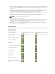
Features Supported Dell PowerEdge 12th generation servers Dell PowerEdge 13th generation servers Unattended operating system installation — Microsoft Windows Unattended operating system installation — Red Hat Enterprise Linux 7 Deploying an operating system using UEFI Secure Boot Enhanced repurpose or retire server NOTE: Specific component selection is not supported on the Dell's 12th generation of PowerEdge servers. For more information on this feature, see Repurpose or retire system.
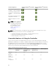
Feature Base Management with IPMI iDRAC Express (Rack and Tower Servers) iDRAC Express (Blade Servers) iDRAC Enterprise Diagnostics Yes Yes Yes Yes Server profile backup and export — — — Yes Server profile import Yes Yes Yes Yes Part replacement — Yes Yes Yes Local updates Yes Yes Yes Yes Driver packs Yes Yes Yes Yes Hardware inventory Yes Yes Yes Yes Remote services — (through WSMAN) Yes Yes Yes Technical Support Report (TSR) Yes Yes Yes Yes Repurpose or ret
Other documents you may need In addition to this guide, you can access the following guides available at dell.com/support/home. • The Lifecycle Controller Online Help provides detailed information about the fields available on the GUI and the descriptions for the same. To view the online help information, click Help in the upperright corner of all Lifecycle Controller pages, or press . • The Lifecycle Controller Release Notes is available from within the product.
forums, white papers, how-to videos, and so on from the Lifecycle Controller wiki page at www.delltechcenter.com/lc. For Lifecycle Controller documents and other related firmware documents, see Dell TechCenter. Accessing documents from Dell support site You can access the required documents in one of the following ways: • Using the following links: – For all Enterprise Systems Management documents — Dell.com/SoftwareSecurityManuals – For OpenManage documents — Dell.
2 Using Lifecycle Controller This section provides information about starting, enabling, and disabling Lifecycle Controller. Before using Lifecycle Controller, make sure that the network and iDRAC are configured. For more information, see the Integrated Dell Remote Access Controller User’s Guide at dell.com/esmmanuals. Starting Lifecycle Controller To start Lifecycle Controller, restart the system and press during POST to select Lifecycle Controller from the list displayed.
Message Lifecycle Controller Update Required Cause • • Lifecycle Controller not available Resolution The embedded device that has Enable Lifecycle Controller. For a backup of the product may more information, see Enabling contain corrupted data. Lifecycle Controller. Ungracefully exits Lifecycle Controller for three consecutive times if one of the following conditions occur: – three consecutive unsuccessful attempts to enter Lifecycle Controller GUI.
4. Under Lifecycle Controller, select Disabled. 5. On the System Setup Main Menu page, select Finish to save the settings. 6. Select Yes to restart the system. Canceling Lifecycle Controller actions If Lifecycle Controller causes the system to restart twice, cancel the Lifecycle Controller actions. However, if Lifecycle Controller causes the system to restart the third time, the message Lifecycle Controller update required is displayed, you must enable Lifecycle Controller.
Configuring network settings for a NIC 1. Start Lifecycle Controller. For more information, see Starting Lifecycle Controller. 2. On the left pane, click Settings. 3. On the Settings page, click Network Settings. 4. From the NIC Card drop-down menu, select the NIC port that you want to configure. NOTE: You can use only one NIC at a time to communicate with the network. 5.
Lifecycle Controller features This section provides a brief description about the Lifecycle Controller features and helps you understand how to use the Lifecycle Controller wizards most effectively. Each feature is a wizard in Lifecycle Controller, which supports the following features: • Home — Navigate back to the Home page. • Lifecycle Log — View and export the Lifecycle Controller log, and add a work note to the log.
Operating system deployment 3 The OS Deployment feature allows you to deploy standard and custom operating systems on the managed system. You can also configure RAID before installing the operating system if it is not already configured. Lifecycle Controller allows deploying the operating system using the following options: • Manual installation • Unattended installation. For more information on unattended installation, see Unattended installation. • UEFI Secure Boot.
4. On the Select an Operating System page, select the following and click Next: • Boot Mode — Choose either UEFI or BIOS boot mode depending on the boot configuration of the system for OS installation. • Secure Boot — Allows you to enable or disable the Secure Boot option. Click Enabled to secure the boot process by checking if the drivers are signed with an acceptable digital signature. This option is available only for the UEFI boot mode. For more information on Secure Boot, see UEFI Secure Boot.
The system reboots and starts the operating system installation. For more information on the postreboot scenarios, see Post Reboot Scenarios. Related Concepts UEFI Secure Boot Unattended installation Post reboot scenarios Related Tasks Using the optional RAID configuration Using the optional RAID configuration When you install an operating system, you can: • • Deploy the operating system without configuring RAID.
Install option is available only if the operating system that you have selected for installation is compatible for an unattended installation. To deploy an operating system using the unattended mode, see Installing An Operating System. You can also see the Unattended Installation of Operating Systems from Lifecycle Controller on Dell PowerEdge Servers white paper at Dell TechCenter.
Using the optional RAID configuration Driver access Lifecycle Controller provides a local repository for drivers that are required for installing the operating system. Based on the operating system you want to install, the OS Deployment wizard extracts these drivers and copies them to a temporary directory (OEMDRV) on the managed system. These files are deleted after 18 hours or when you: • Refresh the AC power cycle, which resets the iDRAC.
Using the optional RAID configuration 24
Monitor 4 Using Lifecycle Controller, you can monitor the hardware inventory and events of a server throughout its life cycle.
For more information about the easy-to-use names of the hardware components, see Easy-to-use System Component Names. NOTE: View and export factory-shipped inventory feature is grayed out if the Repurpose or Retire System option is selected, which permanently deletes the factory-shipped inventory.
3. In the right pane, click Hardware Inventory. 4. Click Export Current Inventory or Export Factory Shipped Hardware Inventory. 5. If you are exporting the inventory to a local USB drive, select USB Drive. If you are exporting the file to a shared folder on a network, select Network Share. For more information, see Exporting Hardware Inventory To A USB Drive or Exporting Hardware Inventory To A Network Share.
• Share Name — Type the server IP or host name followed by the root of the network share. Examples: \\192.168.0.120\sharename or \\hostname\sharename. • Domain and User Name — Type the domain and user name required to log on to the network share. If there is no domain, type the user name. • Password — Type the correct password. • File Path — Type the sub-directories, if any. For example, 2015\Nov.
Viewing or exporting current inventory after resetting Lifecycle Controller NOTE: The system automatically turns off after you select the Repurpose or Retire System option. To view or export the current hardware inventory data after resetting Lifecycle Controller: 1. Turn on the system and wait for a few minutes for iDRAC to start functioning. 2.
You can use the filtering and sorting options to view the Lifecycle Log. NOTE: As the system events are generated by various systems management tools, you may not view the events in log immediately after they were logged. To view the Lifecycle Log history and use the filtering options: 1. Start Lifecycle Controller. For more information, see Starting Lifecycle Controller. 2. In the left pane, click Lifecycle Log. 3. In the right pane, click View Lifecycle Log History.
To export the Lifecycle Log: 1. Start Lifecycle Controller. For more information, see Starting Lifecycle Controller. 2. In the left pane, click Lifecycle Log. 3. In the right pane, click Export Lifecycle Log. 4. Select either USB Drive or Network Share. For more information, see Exporting Lifecycle Log To A USB Drive or Exporting Lifecycle Log To A Network Share. When you select Network Share, to verify connection, click Test Network Connection.
NOTE: The following characters are supported for user name and password: – Digits (0–9) – Alphabets (a-z, A-Z) – Hyphen (-) NOTE: Lifecycle Controller allows 256 characters in a path that includes the file name and file extension. For example, if 56 characters are used for file name and extension, only 200 characters can be used for the path. Lifecycle Controller does not support these characters -:, *,?,”,<,>,|,#,%,^, and SPACE.
5 Firmware update Using Lifecycle Controller, the system can be updated using the repositories accessible through FTP or on a locally attached USB drive, DVD, or network share. Use the Firmware Update page to: • View the current version of the installed applications and firmwares. • View a list of available updates. • Select the required updates, downloads (automatic), and then apply the updates to the following components listed in the table.
Component Name Firmware Rollback Out-of-band — Supported? (Yes or System Restart No) Required? In-band — System Restart Required? Lifecycle Controller GUI — Restart Required? NVMe PCIe SSD drives (13th generation PowerEdge servers only) Yes Yes Yes Yes CMC (on PowerEdge FX2 servers) No Yes Yes Yes OS Collector No No No No * Indicates that though a system restart is not required, iDRAC must be restarted to apply the updates.
• NFS NOTE: If you select a local drive for updates, you will not get an option to browse the device you have selected. You must know the name or path of the filename before selecting the local drive. Version compatibility The version compatibility feature enables you to update the component firmware versions that are compatible with system components. In case of compatibility issues, Lifecycle Controller displays upgrade or downgrade error messages during the update.
5. Type or select the appropriate data. 6. Click Next. The Select Updates page is displayed with the catalog file, catalog version, and component names for which the updates are available. 7. Select the components that require an update, and then click Apply. The update process is initiated and the firmware update is completed. After restart, the system is ready to use. NOTE: The system does not restart if operating system driver packs, OS collector tool, or hardware diagnostics are updated.
Related Concepts Comparing firmware versions Related Tasks Using single component DUPs Using a local drive Using a FTP server Using a network share Updating or rolling back devices that affect Trusted Platform Module settings Using a local drive Lifecycle Controller allows you to perform firmware updates using locally available DVDs or USB drives, or virtual media. This flexibility improves the efficiency of the update process when there is a high network traffic.
• The updates are downloaded using the Dell Repository Manager and the repository is created on a USB drive. NOTE: To download the complete repository, make sure that the USB drive has 8 GB free space. • Connect the USB drive to the system. To update using a USB drive: 1. Insert a USB drive to the managed system. Alternatively, you can insert the USB drive to the client system and use the Virtual Media feature to access the USB drive.
• Internal FTP server or service provider’s FTP server — Enter the following details: – User Name — The user name to access the FTP location. – Password — The password to access the FTP location. – File Path or Update package path — Name of the DUP location or subdirectory where the catalog is available. This step is optional for operating system driver source. NOTE: If the catalog file is located in the root folder, do not enter the file name in the File Path or Update package path field.
NOTE: Lifecycle Controller allows 256 characters in a path that includes the file name and file extension. For example, if 56 characters are used for file name and extension, only 200 characters can be used for the path. Lifecycle Controller does not support these characters -:, *,?,”,<,>,|,#,%,^, and SPACE. • Enable Settings — Select this option to enter the following details: – Server — The host name of the proxy server. – Port — The port number of the proxy server.
NOTE: Make sure that the file name for the single component DUPs does not have any blank space. NOTE: Both 32–bit and 64–bit DUPs are supported. In the File Path or Update package path field, enter the name of the DUP (for example, APP_WIN_RYYYZZZ.EXE) or if the DUP is present in a subdirectory, enter both the subdirectory name and name of the DUP (for example, subdirectory\APP_WIN_RYYYZZZ.EXE). NOTE: Lifecycle Controller allows 256 characters in a path that includes the file name and file extension.
• • • • Except for iDRAC firmware, the earlier version of the firmware is not displayed if the current version and the earlier version are the same. Every time a firmware image is updated, the earlier version of the firmware image is backed up. Every time a rollback operation is performed, the previously installed firmware becomes the current version. However, for iDRAC, the previously installed version becomes the current version and the current version is stored as the previous version.
RAID controller, NIC, and BIOS require that a recovery password is entered or a USB drive that contains a recovery key is inserted during the next system restart. For information on how to set TPM settings, see the BIOS User Guide available at dell.com/support/home. When Lifecycle Controller detects that TPM security is set to On with Pre-boot Measurements, a message indicates that certain updates require the recovery password or USB drive with the recovery key.
Configure 6 Lifecycle Controller provides various system configuration wizards. Use the configuration wizards to configure system devices. The Configuration Wizards has: • System Configuration Wizards — This wizard includes LCD Panel Security, iDRAC Settings, System Date and Time Configuration, and vFlash SD card Configuration. • Storage Configuration Wizards — This wizard includes RAID Configuration, Key Encryption, and Break Mirror.
• 6. View Only • Disable Click Finish to apply the changes. Configuring iDRAC To configure iDRAC parameters applicable to the system, such as LAN, common IP settings, IPv4, IPv6, Virtual Media, and LAN user configuration use the iDRAC Settings wizard. NOTE: You can also use the System Setup utility during startup for configuring iDRAC. For more information about the System Setup utility, see Using The System Setup Program And Boot Manager. To configure and manage the iDRAC parameters: 1.
4. Under System Configuration Wizards, click System Time and Date Configuration. The default system time and system date displayed in Lifecycle Controller is the date and time reported by the system BIOS. 5. Modify the System Time and System Date (HH:MM:SS AM or PM), as required. 6. Click Finish to apply the changes. Configuring vFlash SD card Use the licensed feature to enable or disable the vFlash SD card, check the health and properties, and initialize the vFlash SD card.
3. In the right pane, click Configuration Wizards. 4. On the System Configuration Wizards page, click vFlash SD Card Configuration. The vFlash SD Card page is displayed. 5. Click Initialize vFlash to delete all the data present in the vFlash SD card. NOTE: The Initialize vFlash option is not available after you disable the vFlash SD card.
A foreign configuration is a set of physical disk drives containing a RAID configuration that is introduced to the system, but is not managed by the RAID controller to which it is attached. You may have a foreign configuration if physical disk drives have been moved from one RAID controller to another RAID controller. NOTE: Import Foreign Configuration is supported from System Setup → Advanced Hardware Configuration → Device Settings.
• RAID 6 — Stripes data across the physical disks, and uses two sets of parity information for additional data redundancy. If one or two physical disks fail, the data can be rebuilt using the parity information. RAID 6 offers good data redundancy and read performance but slower write performance. • RAID 10 — Combines mirrored physical disks with data striping. If a physical disk fails, data can be rebuilt using the mirrored data. RAID 10 offers good read and write performance with good data redundancy.
• Encryption Capability — Select Yes to enable encryption capability. • Select Span Length — Select the span length. The span length value refers to the number of physical disk drives included in each span. Span length applies only to RAID 10, RAID 50, and RAID 60. The Select Span Length drop‑down list is active only if you have selected RAID 10, RAID 50, or RAID 60.
• Secure Virtual Disk — Select to secure the virtual drive using the controller’s security key. NOTE: The secure virtual drive is created only if the controller security key is created and the selected disks are Self-Encrypting Drives (SEDs). Viewing summary The Summary page displays the virtual disk attributes based on selections. CAUTION: Clicking Finish deletes all existing virtual drives except any foreign configurations that you specified. All data residing on the virtual drives is lost.
The Virtual Disk Attributes page is displayed. 8. Select the virtual disk parameters and click Next. The Summary page is displayed. 9. To apply the RAID configuration, click Finish. Related Concepts Selecting a RAID controller Foreign configuration found Selecting RAID levels Selecting physical disks Setting virtual disk attributes Viewing summary Creating a secure virtual disk on a RAID controller Make sure that the controller is encrypted with a local key.
Viewing summary Related Tasks Applying the local key on a RAID controller Key encryption Use the Key Encryption feature to: • Apply local encryption for PERC H710, H710P, H730, H730P, H810, and H830 RAID controllers. • Delete the local encryption key. • Encrypt the existing unsecure virtual drives. • To change an existing encryption key to another one. NOTE: For more information about the key encryption feature, see the Key Encryption in Lifecycle Controller white paper at delltechcenter.com/lc.
NOTE: This option is available if there are secure-capable virtual disks connected to a securitycapable controller. • Rekey controller and encrypted disks with a new key — Replace the existing local key with a new key. • Remove encryption and delete data — Delete the encryption key on the controller and all the secure virtual drives along with its data. After deletion, controller state changes to No encryption mode.
8. In the New Passphrase field, enter the passphrase that is associated with the new encryption key identifier. Related Concepts Local key encryption mode Removing encryption and deleting data To remove the encryption and delete the data on the virtual disks: CAUTION: The existing encryption, virtual drives, and all the data are permanently deleted. 1. Start Lifecycle Controller. For more information, see Starting Lifecycle Controller. 2. In the left pane, click Hardware Configuration. 3.
NOTE: When you update the firmware on a BCM57xx and 57xxx adapters, you will notice that the cards are displayed as QLogic. This is due to the acquisition of Broadcom NetXtreme II by QLogic. The Advanced Hardware Configuration wizard allows you to configure the following: NOTE: You can also use System Setup utility during startup to configure the following devices. For more information about the System Setup utility, see Using The System Setup Program And Boot Manager.
– Intel i540 DP 10G BASE-T Adapter (Full Height) – Intel i540 DP 10G BASE-T Adapter (Low Profile) – Intel DP 10GBASE SFP+ (Full Height) – Intel DP 10GBASE SFP+ (Low Profile) – Intel i350 DP 1G Adapter (Full Height) – Intel i350 DP 1G Adapter (Low Profile) – Intel i350 QP 1G Adapter (Full Height) – Intel i350 QP 1G Adapter (Low Profile) – Intel i540 QP rNDC (10G BASE-T + 1G BASE-T) – Intel i350 QP rNDC 1G BASE-T – Intel i520 DP bNDC KR – Intel DP 10Gb KR Mezz – Intel DP 10Gb KR Mezz – Intel I350 QP 1G Mezz –
• H310 Mini Blades • H310 Embedded • H330 Adapter • H330 Mini Monolithic • H330 Mini Blades • H330 Embedded • H710 Adapter • H710 Mini Blades • H710 Mini Monolithic • H710P Adapter • H710P Mini Blades • H710P Mini Monolithic • H810 Adapter • H830 Adapter • H730P Adapter • PERC S110 • PERC S130 Integrated Broadcom NICs are controlled by both BIOS and the settings stored on the device itself.
Collect system inventory on restart When you enable the Collect System Inventory On Restart (CSIOR) property, hardware inventory and part configuration information is discovered and compared with previous system inventory information on every system restart. NOTE: By default, the CSIOR property is enabled. Updating server inventory information To enable collecting system inventory on restart: 1. Start Lifecycle Controller. For more information, see Starting Lifecycle Controller. 2.
3. Use this local FTP server for firmware update. Using Dell Repository Manager to create the repository and copy it to a local FTP server To create and copy the repository: 1. Copy the repository created using the Dell Repository Manager to the root directory of the local FTP server. NOTE: For information about creating a repository for your system, see the Dell Repository Manager User’s Guide at dell.com/support/home. 2. Use this local FTP server for firmware update.
NOTE: A USB drive is not required for users, who have access to ftp.dell.com through a proxy server. For the latest updates, download the most recent Dell Server Updates ISO images for your system from dell.com/support. NOTE: Lifecycle Controller supports internal SATA optical drives, USB drives, and Virtual Media devices. If the installation media is corrupt or not readable, then Lifecycle Controller may be unable to detect the presence of a media.
Configuring CIFS servers To configure an CIFS server, perform the following tasks: 1. Right-click the folder that you want to configure as CIFS share and select Properties → Sharing. 2. Click the Advanced Sharing tab and select Share this folder. 3. Click the Permissions tab. 4. Click Add to add names of the users for whom you want to provide access to the CIFS share. 5. Type the names and click OK. 6. In the Permissions section under Allow column, select Full Control.
Maintain 7 Using Lifecycle Controller, you can maintain the health of a system throughout its life cycle using the features such as Part Replacement Configuration and Platform Restore. Platform restore Lifecycle Controller allows you to create a copy (image file) of the server's profile on the vFlash SD card installed on the server.
– Component configuration information. – User name and password for RAID controller and BIOS. – Component certificates. – Licenses. – Signature to validate that the backup file is not tampered and generated by Lifecycle Controller. The server profile backup image file does not contain: • Operating system or any data stored on hard-disk drives or virtual drives. • vFlash SD card partition information. • Lifecycle log. • Dell diagnostics. • Dell OS Driver Pack.
Component Firmware Configuration Security Information* Lifecycle Controller Yes NA NA Backplane NA NA NA CPLD NA NA NA Power Supply Unit Yes NA NA FC HBA Yes Yes NA Enclosure NA NA NA NVMe PCIe SSD drives NA NA NA OS Collector NA NA NA HHHL NVMe Adapter NA NA NA * The security information refers to the user credentials that are used to access the components.
3. In the right pane, select Backup Server Profile. 4. To generate the backup file without entering the passphrase, click Finish. Alternatively, to generate an encrypted backup file using a passphrase, enter the passphrase and click Finish. In the absence of a passphrase, Lifecycle Controller encrypts the backup image file with a default passphrase (internally generated). 5. In the Backup File Passphrase field, enter a passphrase. For example, Rt@#12tv.
To export the server profile to a USB drive or a network share: 1. Start Lifecycle Controller. For more information, see Starting Lifecycle Controller. 2. In the left pane, select Platform Restore. 3. In the right pane, select Export Server Profile. 4. Select either USB Drive or Network Share, enter the details, and then click Finish. NOTE: You can also use a USB drive that is attached to the client system while operating remotely. To use the USB drive remotely, use the Virtual Media feature.
Importing server profile from a vFlash SD card, network share, or USB drive Before importing the server profile, make sure that the following prerequisites are met: • The Service Tag of the server is same as when the backup was taken. • If you are restoring from a vFlash SD card, the vFlash SD card must be installed and must contain the backup image in a folder labeled SRVCNF. This image must be from the same server that you are trying to restore.
5. Click Network Share. 6. Select CIFS or NFS, enter the backup file name along with the directory, subdirectory path, and then click Next. 7. Select either Preserve or Delete. 8. • Delete configuration — Deletes the RAID level, virtual disk, and controller attributes. If you have secured the backup image file with a passphrase, enter the passphrase (entered during backup) in the Backup File Passphrase field, and then click Finish.
• Import operation for a card fails if the slot in which it was installed earlier has changed. • The import operation restores only Perpetual license. The Evaluation license is not restored only if it has not expired. Post-import scenario The managed-system performs the following operations: 1. The system if turned on, automatically turns off. If the system boots to an operating system, it attempts to perform a graceful shutdown.
Restoring a server profile after system board replacement When you launch Lifecycle Controller after replacing the system board, a message is displayed prompting you to either retrieve the Service Tag and the server profile from a vFlash SD card that contains the backed-up server profile or manually enter the Service Tag in case you have not backed up the server. To restore the server profile: 1. Press during POST to launch Lifecycle Controller. 2.
Importing an iDRAC license from a network share To import a server license from a network share: 1. Start Lifecycle Controller. For more information, see Starting Lifecycle Controller. 2. In the left pane, click Platform Restore. 3. In the right pane, click Import Server License. 4. On the Import Server License page, click Network Share. 5. Click Yes, if the following message appears: Network is not configured. Do you want to configure now?.
Applying firmware and configuration updates to replaced parts Before configuring replaced parts, make sure that the following prerequisites are met: • Click the Collect System Inventory On Restart option, so that Lifecycle Controller automatically invokes Part Firmware Update and Part Configuration Update when the system is started.
• Power Supply Unit (PSU) NOTE: PSUs support only firmware update and not part replacement. Repurpose or retire system You can erase selective system information by using the Lifecycle Controller Repurpose or Retire System option. This feature permanently deletes server and storage-related data on selected components of a server before you repurpose or retire a server. The selected components are then returned to their default state.
Hardware diagnostics It is recommended that you run diagnostics using the Hardware Diagnostics utility, as part of a regular maintenance plan to validate whether or not the system and the attached hardware are functioning properly. As the diagnostics utility has a physical (as opposed to logical) view of the attached hardware, it can identify hardware problems that the operating system and other online tools cannot identify.
NOTE: OS and Software application data is enabled only if this data is already collected and cached using the OS collector tool on iDRAC. Lifecycle Controller displays this option along with the time stamp of data collection. You can select this option to retrieve the cached data available on the server. For more information on collecting OS and Software application data using the OS collector tool in iDRAC, see the Integrated Dell Remote Access Controller (iDRAC) User’s Guide at dell.com/esmmauals.
5. 6. 7. On the Select Report Data page, select the options for which you want to create a technical support report: • Hardware — Collects data pertaining to the server and component inventory, firmware installed on the server, configuration information, and hardware logs. • RAID Controller Logs — Contains information about the storage logs. • Operating System and Application Data — Contains information about the operating system and application.
Easy-to-use system component names 8 The following table lists the Fully Qualified Device Descriptor (FQDD) of the system components and the equivalent easy-to-use names. Table 8. Easy-to-use Names of System Components FQDD of System Component Name Easy-to-use Name RAID.Integrated.1-1 Integrated RAID Controller 1 RAID.Slot.1-1 RAID Controller in Slot 1 NIC.Mezzanine.1B-1 NIC in Mezzanine NIC.Mezzanine.1C-1 NIC.Mezzanine.1C-2 NIC.Mezzanine.3C-2 NonRAID.Integrated.
FQDD of System Component Name Easy-to-use Name P2PBridge.Mezzanine.2B-1 Embedded Host Bridge in Mezzanine 1 (Fabric B) USBUHCI.Embedded.1-1 Embedded USB UHCI 1 USBOHCI.Embedded.1-1 Embedded USB OHCI 1 USBEHCI.Embedded.1-1 Embedded USB EHCI 1 Disk.SATAEmbedded.A-1 Disk on Embedded SATA Port A Optical.SATAEmbedded.B-1 Optical Drive on Embedded SATA Port B TBU.SATAExternal.C-1 Tape Back-up on External SATA Port C Disk.USBFront.1-1 Disk connected to front USB 1 Floppy.USBBack.
FQDD of System Component Name Easy-to-use Name Fan.Slot. 1 Fan 1 Fan.Slot. 2 Fan 2 … … Fan.Slot. 9 Fan 9 MC.Chassis.1 Chassis Management Controller 1 MC.Chassis.2 Chassis Management Controller 2 KVM.Chassis.1 KVM IOM.Slot.1 IO Module 1 … … IOM.Slot.6 IO Module 6 PSU.Slot.1 Power Supply 1 … ... PSU.Slot.6 Power Supply 6 CPU.Socket.1 CPU 1 System.Modular.2 Blade 2 DIMM.Socket.
Using the System Setup and boot manager 9 System Setup enables you to manage your system hardware and specify BIOS-level options. The following keystrokes provide access to system features during startup: Table 9. System setup keystrokes Keystroke Description Opens the System Setup page. Opens and starts Lifecycle Controller, which supports systems management features such as operating system deployment, hardware diagnostics, firmware updates, and platform configuration, using a GUI.
Choosing the system boot mode System Setup enables you to specify one of the following boot modes for installing your operating system: • BIOS boot mode (the default) is the standard BIOS-level boot interface. • Unified Extensible Firmware Interface (UEFI) boot mode is an enhanced 64-bit boot interface. If you have configured your system to boot to UEFI mode, it overlays the system BIOS. 1. From the System Setup Main Menu, click Boot Settings and select Boot Mode. 2.
Spacebar Expands or collapses a drop-down menu, if applicable. Moves to the next focus area. NOTE: For the standard graphics browser only. Moves to the previous page till you view the main screen. Pressing in the main screen displays a message that prompts you to save any unsaved changes and restarts the system. Displays the System Setup help file. NOTE: For most of the options, any changes that you make are recorded but do not take effect until you restart the system.
Menu Item Description Serial Communication Displays options to enable or disable the serial ports and specify related features and options. System Profile Settings Displays options to change the processor power management settings, memory frequency, and so on. System Security Displays options to configure the system security settings like, system password, setup password, TPM security, and so on. It also enables or disables support for local BIOS update, the power and NMI buttons on the system.
Menu Item Description Memory Operating Specifies the memory operating mode. The options available are Optimizer Mode, Mode Advanced ECC Mode, Mirror Mode, Spare Mode, Spare with Advanced ECC Mode, and Dell Fault Resilient Mode. By default, the Memory Operating Mode option is set to Optimizer Mode. NOTE: The Memory Operating Mode can have different defaults and available options based on the memory configuration of your system.
Menu Item Description DCU Streamer Prefetcher Allows you to enable or disable the Data Cache Unit (DCU) streamer prefetcher. By default, the DCU Streamer Prefetcher option is set to Enabled. DCU IP Prefetcher Allows you to enable or disable the Data Cache Unit (DCU) IP prefetcher. By default, the DCU IP Prefetcher option is set to Enabled. Execute Disable Allows you enable or disable execute disable memory protection technology. By default, the Execute Disable option is set to Enabled.
Menu Item Description Port B Auto enables BIOS support for the device attached to SATA port B. By default, Port B is set to Auto. Port C Auto enables BIOS support for the device attached to SATA port C. By default, Port C is set to Auto. Port D Auto enables BIOS support for the device attached to SATA port D. By default, Port D is set to Auto. Port E Auto enables BIOS support for the device attached to SATA port E. By default, Port E is set to Auto.
Integrated devices screen Menu Item Description Integrated RAID Controller Allows you to enable or disable the integrated RAID controller. By default, the Integrated RAID Controller option is set to Enabled. User Accessible USB Ports Allows you enable or disable the user accessible USB ports. Selecting Only Back Ports On disables the front USB ports and selecting All Ports Off disables both front and back USB ports. By default, the User Accessible USB Ports option is set to All Ports On.
Serial communications screen Menu Item Description Serial Communication Allows you to select serial communication devices (Serial Device 1 and Serial Device 2) in the BIOS. BIOS console redirection can also be enabled and the port address can be specified. By default, Serial Communication option is set to On without Console Redirection. Serial Port Address Allows you to set the port address for serial devices.
Menu Item Description Memory Frequency Allows you to set the memory frequency. By default, the Memory Frequency option is set to Maximum Performance. Turbo Boost Allows you to enable or disable the processor to operate in turbo boost mode. By default, the Turbo Boost option is set to Enabled. C1E Allows you to enable or disable the processor to switch to a minimum performance state when it is idle. By default, the C1E option is set to Enabled.
Menu Item Description Status, TPM Activation , and Intel TXT fields if the TPM Status field is set to either On with Pre-boot Measurements or On without Pre-boot Measurements. TPM Activation Allows you to change the operational state of the TPM. By default, the TPM Activation option is set to No Change. TPM Status Displays the TPM status. TPM Clear CAUTION: Clearing the TPM results in the loss of all keys in the TPM. The loss of TPM keys may affect booting to the operating system.
Menu Item Description System Date Allows you to set the date on the system. Asset Tag Displays the asset tag and allows you to modify it for security and tracking purposes. Keyboard NumLock Allows you to set whether the system boots with the NumLock enabled or disabled. By default the Keyboard NumLock is set to On. NOTE: This option does not apply to 84-key keyboards. Report Keyboard Errors Allows you to set whether keyboard-related error messages are reported during system boot.
3. In the System BIOS screen, select System Security and press Enter. 4. In the System Security screen, verify that Password Status is Unlocked. 5. Select System Password, enter your system password, and press Enter or Tab. Use the following guidelines to assign the system password: • A password can have up to 32 characters. • The password can contain the numbers 0 through 9. • Only the following special characters are allowed: space, (”), (+), (,), (-), (.), (/), (;), ([), (\), (]), (`).
When Password Status is set to Locked, type the password and press Enter when prompted at reboot. NOTE: If an incorrect system password is typed, the system displays a message and prompts you to reenter your password. You have three attempts to type the correct password. After the third unsuccessful attempt, the system displays an error message that the system stops functioning and must be turned off.
Using the boot manager navigation keys Key Description Up arrow Moves to the previous field. Down arrow Moves to the next field. Allows you to type in a value in the selected field (if applicable) or follow the link in the field. Spacebar Expands or collapses a drop-down list, if applicable. Moves to the next focus area. NOTE: For the standard graphics browser only. Moves to the previous page till you view the main screen.
Menu Item Description Add Boot Option Adds a new boot option. Delete Boot Option Deletes an existing boot option. Boot From File Sets a one-time boot option not included in the boot option list. Embedded system management The Dell Lifecycle Controller provides advanced embedded systems management throughout the server’s lifecycle. The Dell Lifecycle Controller can be started during the boot sequence and can function independently of the operating system.
Troubleshooting and frequently asked questions 10 This section describes the error messages commonly generated by Lifecycle Controller and provides suggestions for resolving the issues. This section also lists the questions that are frequently asked by Lifecycle Controller users. Error messages Each error message that is generated from Lifecycle Controller has a Message ID, Message Description, and Recommended Response Action in a single dialog box.
7. Can I update the drivers used by an already-installed operating system through Lifecycle Controller? No, Lifecycle Controller only provides drivers that are required for operating system installation. To update the drivers used by an installed operating system, see your operating system’s Help documentation. 8. Can I add my own drivers and firmware for updating Lifecycle Controller to a local USB drive? No, only drivers and firmware downloaded from the Dell Server Updates DVD are supported.
17. How do I find out the currently installed version details of the Lifecycle Controller product? Click About on the top right corner of the Lifecycle Controller home page. 18. What should I do if I have an issue with mouse cursor synchronization when I access Lifecycle Controller through the iDRAC Virtual Console? Make sure that the Single Cursor option under Tools menu is selected on the iDRAC Virtual Console client.