Dell Lifecycle Controller GUI v2.50.50.
Notes, cautions, and warnings NOTE: A NOTE indicates important information that helps you make better use of your product. CAUTION: A CAUTION indicates either potential damage to hardware or loss of data and tells you how to avoid the problem. WARNING: A WARNING indicates a potential for property damage, personal injury, or death. Copyright © 2017 Dell Inc. or its subsidiaries. All rights reserved. Dell, EMC, and other trademarks are trademarks of Dell Inc. or its subsidiaries.
Contents 1 Introduction....................................................................................................................................................7 Using Lifecycle Controller..................................................................................................................................................7 Benefits of using iDRAC with Lifecycle Controller.........................................................................................................
Viewing or exporting hardware inventory after part replacement............................................................................. 30 Viewing or exporting current inventory after resetting Lifecycle Controller............................................................ 30 Lifecycle Controller log.....................................................................................................................................................31 Viewing Lifecycle Log history.........................
FTP authentication.................................................................................................................................................... 59 Requirements for a local FTP server....................................................................................................................... 59 Copying repository to a local FTP server from the Dell Server Updates DVD...................................................
System BIOS screen..................................................................................................................................................82 System information screen....................................................................................................................................... 83 Memory Settings screen...........................................................................................................................................
1 Introduction Dell Lifecycle Controller provides advanced embedded systems management to perform systems management tasks such as deploy, configure, update, maintain, and diagnose using a graphical user interface (GUI). It is delivered as part of integrated Dell Remote Access Controller (iDRAC) out-of-band solution and embedded Unified Extensible Firmware Interface (UEFI) applications in the latest Dell servers.
Benefits of using iDRAC with Lifecycle Controller The benefits include: • Increased availability — Early notification of potential or actual failures that help prevent a server failure or reduce recovery time after failure. • Improved productivity and lower Total Cost of Ownership (TCO) — Extending the reach of administrators to larger number of distant servers can make the IT staff more productive while driving down operational costs such as travel.
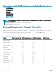
Feature matrix The following table lists the Lifecycle Controller features supported on the 12th and 13th generation Dell PowerEdge servers. Table 1.
Dell PowerEdge 12th generation servers Features supported Dell PowerEdge 13th generation servers NOTE: Specific component selection is not supported on the Dell's 12th generation of PowerEdge servers. For more information on this feature, see Repurpose or retire system. NOTE: The following features are supported on the 12th generation PowerEdge servers only if iDRAC and Lifecycle Controller versions are 2.10.10.
Feature Basic Management with IPMI iDRAC Express (Rack and iDRAC Express (Blade Tower Servers) Servers) iDRAC Enterprise SupportAssist Collection Yes Yes Yes Yes Repurpose or retire system Yes Yes Yes Yes Viewing iDRAC license information After you open the Lifecycle Controller GUI page, you can view details about the iDRAC installed on a server. To view the iDRAC license information: 1 Start Lifecycle Controller. For more information, see Starting Lifecycle Controller.
The following system documents are available to provide more information: • The safety instructions that came with your system provide important safety and regulatory information. For additional regulatory information, see the Regulatory Compliance home page at dell.com/regulatory_compliance. Warranty information may be included within this document or as a separate document. • The Rack Installation Instructions included with your rack solution describe how to install your system into a rack.
Dell provides several online and telephone-based support and service options. Availability varies by country and product, and some services may not be available in your area. To contact Dell for sales, technical support, or customer service issues: 1 Go to Dell.com/support. 2 Select your support category. 3 Verify your country or region in the Choose a Country/Region drop-down list at the bottom of the page. 4 Select the appropriate service or support link based on your need.
2 Using Lifecycle Controller This section provides information about starting, enabling, and disabling Lifecycle Controller. Before using Lifecycle Controller, make sure that the network and iDRAC are configured. For more information, see the Integrated Dell Remote Access Controller User’s Guide at dell.com/esmmanuals.
Message Cause Resolution Lifecycle Controller update required • Enable Lifecycle Controller. For more information, see Enabling Lifecycle Controller. • Lifecycle Controller not available The embedded device that has a backup of the product may contain corrupted data. Ungracefully exits Lifecycle Controller for three consecutive times if one of the following conditions occur: • 3 consecutive unsuccessful attempts to enter Lifecycle Controller GUI.
Canceling Lifecycle Controller actions If Lifecycle Controller causes the system to restart twice, cancel the Lifecycle Controller actions. However, if Lifecycle Controller causes the system to restart the third time, the message Lifecycle Controller update required is displayed, you must enable Lifecycle Controller. For more information on enabling Lifecycle Controller, see Enabling Lifecycle Controller. CAUTION: This action cancels all tasks that are being performed by Lifecycle Controller.
Configuring Lifecycle Controller Network Settings Use this page to configure network settings for a NIC. 1 Start Lifecycle Controller. For more information, see Starting Lifecycle Controller. 2 On the left pane, click Settings. 3 On the Settings pane, click Network Settings. 4 From the NIC Card drop-down menu, select the NIC port that you want to configure. NOTE: You can use only one NIC at a time to communicate with the network.
• Static — indicates that the network must be configured by using a static IP. Type the IP Address Properties such as IP Address, Subnet Mask, Default Gateway, DNS Address Source, and DNS Address. If you do not have this information, contact your network administrator. • DHCP — Indicates that the network must be configured by using an IP address from a DHCP server. If DHCP is selected, a DHCP IP address is displayed on the Network Settings page.
Viewing summary of network settings This page provides a summary of the Lifecycle Controller and iDRAC IP configurations. Verify the configurations and click Finish to save the settings and exit from the Settings wizard. Accessing help Each Lifecycle Controller page has a help associated with it. Press or click Help (in the upper-right corner) to view the help information about the features available on a page.
6 From the IPV6 Network Settings→ IP Address Source drop-down menu, select one of the following options: • No Configuration — indicates that the NIC must not be configured. • DHCPv6 — indicates that the NIC must be configured using an IP address from a DHCPv6 server. If DHCPv6 is selected, a DHCPv6 IP address is displayed on the Network Settings page. NOTE: While configuring DHCP server with IPv6, the configuration fails if you disable forwarding or advertising options.
Related link Lifecycle Controller log Firmware update Firmware rollback Hardware inventory view and export Configure Operating system deployment Platform restore Hardware diagnostics Setting up Lifecycle Controller using Initial Setup Wizard Using the system setup and boot manager Import server license Viewing iDRAC license information Restoring server profile after system board replacement Using Lifecycle Controller 21
3 Operating system deployment The OS Deployment feature allows you to deploy standard and custom operating systems on the managed system. You can also configure RAID before installing the operating system if it is not already configured. Lifecycle Controller allows deploying the operating system using the following options: • Manual installation • Unattended installation. For more information on unattended installation, see Unattended installation. • UEFI Secure Boot.
NOTE: Configuring RAID is optional if an already-connected virtual disk is present. • 4 Go Directly to OS Deployment — Click to launch the operating system deployment wizard and start installing an operating system. On the Select an Operating System page, select the following and click Next: • Boot Mode — Choose either UEFI or BIOS boot mode depending on the boot configuration of the system for OS installation. • Secure Boot — Allows you to enable or disable the Secure Boot option.
Related link UEFI Secure Boot Unattended installation Post reboot scenarios Using the optional RAID configuration Using the optional RAID configuration When you install an operating system, you can: • Deploy the operating system without configuring RAID. • Configure the hard-disk drives using the optional RAID configuration wizard and deploy the operating system.
UEFI Secure Boot The UEFI Secure Boot is a technology that secures the boot process by verifying if the drivers and operating system loaders are signed by the key that is authorized by the firmware. When enabled, Secure Boot makes sure that: • BIOS boot option is disabled. • Only UEFI-based operating systems are supported for operating system deployment in all management applications. • Only authenticated EFI images and operating system loaders are started from UEFI firmware.
Post reboot scenarios The following table lists the post reboot scenarios, its user actions, and impact. Table 7. Post reboot scenarios Scenario User Action and Impact During POST, the system prompts you to press a key to boot to the operating system installation media. Press any key to begin the operating system installation; else, the system boots to the hard-disk drive and not the operating system installation media.
4 Monitor Using Lifecycle Controller, you can monitor the hardware inventory and events of a server throughout its life cycle.
About view and export factory-shipped inventory You can view information about the factory-installed hardware components and their configuration. You can export this information in an XML format to a USB drive or a network share. The XML file is saved in this format: FactoryShippedHWInventory_.xml. For more information about the easy-to-use names of the hardware components, see Easy-to-use System Component Names.
3 In the right pane, click Hardware Inventory. 4 Click Export Current Inventory or Export Factory Shipped Hardware Inventory. 5 If you are exporting the inventory to a local USB drive, select USB Drive. If you are exporting the file to a shared folder on a network, select Network Share. For more information, see Exporting Hardware Inventory To A USB Drive or Exporting Hardware Inventory To A Network Share.
• Password — Type the correct password. • File Path — Type the sub-directories, if any. For example, 2015\Nov. NOTE: The following characters are supported for user name and password: • Digits (0–9) • Alphabets (a-z, A-Z) • Hyphen (-) NOTE: Lifecycle Controller allows 256 characters in a path that includes the file name and file extension. For example, if 56 characters are used for file name and extension, only 200 characters can be used for the path.
To view or export the current hardware inventory data after resetting Lifecycle Controller: 1 Turn on the system and wait for a few minutes for iDRAC to start functioning. 2 Press during POST to start Lifecycle Controller and the system inventory is collected as Collect System Inventory On Restart (CSIOR) is enabled by default.
The following details are displayed: • No. — The serial number of the event. • Category — The category to which the events belong. The available categories are: • All — Events related to all categories are listed. • System Health — Events related to the installed hardware such as fan, PSUs, NIC/LOM/CNA link, BIOS errors, and so on. • Storage — Events related to the external or internal storage components such as storage controller, enclosure, HDDs, and software RAID.
NOTE: Lifecycle Controller cannot ping the domain name and cannot display the IP address if the DNS is not able to resolve the domain name. Make sure that the issue with DNS is resolved and retry. 5 Click Finish. The Lifecycle Log is exported to the specified location.
The examples provided for Share Name and File Path are in the correct format even though it does not follow the mount behavior for NFS shares. NOTE: Lifecycle Controller allows 256 characters in a path that includes the file name and file extension. For example, if 56 characters are used for file name and extension, only 200 characters can be used for the path. Lifecycle Controller does not support these characters -:, *,?,”,<,>,|,#,%,^, and SPACE.
5 Firmware update Using Lifecycle Controller, the system can be updated using the repositories accessible through FTP or on a locally attached USB drive, DVD, or network share. Use the Firmware Update page to: • • • View the current version of the installed applications and firmware. View a list of available updates. Select the required updates, downloads (automatic), and then apply the updates to the following components listed in the table.
Topics: • Firmware update methods • Version compatibility • Updating firmware • Firmware rollback Related link Firmware update methods Version compatibility Updating firmware Firmware update methods The following table lists the various locations or media and methods to perform the updates: NOTE: If the FTP server or network share is used for updates, configure the network card using the Settings wizard before accessing the updates. Table 9.
.D7 Image iDRAC DUP Racadm FWUpdate (old) Yes No No N/A Racadm Update (new) Yes Yes Yes Yes iDRAC UI Yes Yes Yes Yes WSMAN Yes Yes Yes Yes In-band OS DUP No N/A Yes No Version compatibility The version compatibility feature enables you to update the component firmware versions that are compatible with system components. In case of compatibility issues, Lifecycle Controller displays upgrade or downgrade error messages during the update.
NOTE: If you select Network Share (CIFS, NFS, or HTTP), you can verify the connection by clicking Test Network Connection. By default, Lifecycle Controller pings the host and proxy IP. 5 Type or select the appropriate data. 6 Click Next. The Select Updates page is displayed with the catalog file, catalog version, and component names for which the updates are available. 7 Select the components that require an update, and then click Apply.
Related link Comparing firmware versions Using single component DUPs Using a local drive Using a FTP server Using a network share Updating or rolling back devices that affect Trusted Platform Module settings Using a local drive Lifecycle Controller allows you to perform firmware updates using locally available DVDs or USB drives, or virtual media. This flexibility improves the efficiency of the update process when there is a high network traffic.
To update using a USB drive: 1 Insert a USB drive to the managed system. Alternatively, you can insert the USB drive to the client system and use the Virtual Media feature to access the USB drive. For more information about this feature, see the Integrated Dell Remote Access Controller (iDRAC) User’s Guide at dell.com/esmmanuals. 2 From the Select Device drop-down menu, select the USB drive that contains the updates (DUP or repository).
Using a proxy FTP server Using Lifecycle Controller, you can update the firmware by using ftp.dell.com, or by using an internal FTP server or service provider’s FTP server, when you are connected to the Internet through a proxy server. Before performing an update using a proxy FTP server, make sure that the following prerequisites are met: • The network settings are configured (Settings > Network Settings).
For NFS, type the following details: • Share Name — Path to the repository or the shared folder where the DUPs are stored. For example, \\192.168.20.26\sharename or \\servername\sharename • File Path or Update package path — Name of the DUP location or subdirectory, where the catalog is stored. NOTE: If the catalog file is located in the root folder, do not enter the filename in the File Path or Update package path field.
Release Date: YYYY-MM-DD Source: USB Drive or CD or DVD (): \. By default, Lifecycle Controller selects the components for which the current updates are available. 2 Click Apply. The system may restart after the update process is complete. When applying more than one update, the system may restart between the updates and launch back to Lifecycle Controller, and continue with the other selected updates.
After the update process is complete, the system may restart. When applying more than one update, the system may restart between updates and launch back to Lifecycle Controller and continue updating.
6 Configure Lifecycle Controller provides various system configuration wizards. Use the configuration wizards to configure system devices. The Configuration Wizards has: • System Configuration Wizards — This wizard includes LCD Panel Security, iDRAC Settings, System Date and Time Configuration, and vFlash SD card Configuration. • Storage Configuration Wizards — This wizard includes RAID Configuration, Key Encryption, and Break Mirror.
• View Only — You can move through the data screens to obtain information using the system control panel interface. • Disable — You do not have access to information or control, other than the information displayed by the management controller, and you cannot specify actions. Controlling access to the front panel To control access to the front panel: 1 Start Lifecycle Controller. For more information, see Starting Lifecycle Controller.
5 • Reset iDRAC Configuration to defaults Click Back after setting the parameters for each option to return to the main menu. 6 Click Finish to apply the changes. Configuring system time and date To set the time and date for the managed system: 1 Start Lifecycle Controller. For more information, see Starting Lifecycle Controller. 2 From the Lifecycle Controller Home page, select Hardware Configuration. 3 In the right pane, select Configuration Wizards.
The vFlash SD Card page is displayed. 5 From the vFlash SD card drop-down menu, select Enabled or Disabled. 6 Click Finish to apply the changes. Initializing a vFlash SD card 1 Start Lifecycle Controller. For more information, see Starting Lifecycle Controller. 2 In the left pane, click Hardware Configuration. 3 In the right pane, click Configuration Wizards. 4 On the System Configuration Wizards page, click vFlash SD Card Configuration. The vFlash SD Card page is displayed.
Foreign configuration found The Foreign Configuration Found page is displayed only if a foreign configuration physical disk drive resides on the selected RAID controller or any uninitialized physical disk drives present on the system. A foreign configuration is a set of physical disk drives containing a RAID configuration that is introduced to the system, but is not managed by the RAID controller to which it is attached.
• • • • RAID 6 — Stripes data across the physical disks, and uses two sets of parity information for additional data redundancy. If one or two physical disks fail, the data can be rebuilt using the parity information. RAID 6 offers good data redundancy and read performance but slower write performance. RAID 10 — Combines mirrored physical disks with data striping. If a physical disk fails, data can be rebuilt using the mirrored data.
the data on the disk and return these values on a read request. When you read or write the data from the HDD, the data is checked for the errors. Select one of the following types of T10 protection information capabilities : • All — indicates that both the T10 PI capable and non-capable HDDs are selected. • T10 PI Capable — indicates that only T10 PI capable HDDs are selected. • Non-T10 Capable — indicates that only non-T10 capable HDDs are selected. NOTE: PERC 9 with version 9.3.
NOTE: The secure virtual drive is created only if the controller security key is created and the selected disks are SelfEncrypting Drives (SEDs). Viewing summary The Summary page displays the virtual disk attributes based on selections. CAUTION: Clicking Finish deletes all existing virtual drives except any foreign configurations that you specified. All data residing on the virtual drives is lost. To return to a previous page to review or change selections, click Back.
Related link Selecting a RAID controller Foreign configuration found Selecting RAID levels Selecting physical disks Setting virtual disk attributes Viewing summary Creating a secure virtual disk on a RAID controller Make sure that the controller is encrypted with a local key. For more information on encrypting with a local key, see Key Encryption. To create a secure virtual disk on a RAID controller: 1 Start Lifecycle Controller. For more information, see Starting Lifecycle Controller.
• Encrypt the existing unsecure virtual drives. • To change an existing encryption key to another one. NOTE: For more information about the key encryption feature, see the Key Encryption in Lifecycle Controller white paper at delltechcenter.com/lc. Applying the local key on a RAID controller Before applying the local key on a RAID controller, make sure that the controller is security-capable. To apply the local key on a RAID controller: 1 Start Lifecycle Controller.
• Controller must be in the local-key-encryption mode. To encrypt the unsecure virtual drives: NOTE: All virtual drives created on the same physical disk-drives are automatically encrypted when any one of the virtual drives is encrypted. 1 Start Lifecycle Controller. For more information, see Starting Lifecycle Controller. 2 In the left pane, click Hardware Configuration. 3 In the right pane, click Configuration Wizards. 4 On the Storage Configuration wizards page, click Key Encryption.
Breaking mirrored drives To split the mirrored array of RAID-1 virtual drives: 1 Start Lifecycle Controller. 2 In the left pane, click Hardware Configuration. 3 In the right pane, click Configuration Wizards. 4 Under Storage Configuration wizards, click Break Mirror. The Break Mirror page is displayed with the mirrored virtual drives. 5 Select the related controller and click Finish. NOTE: The Break Mirror feature does not support software RAID controllers.
• Broadcom 57810S DP 10G SFP+ Adapter (Full Height) • Broadcom 57810S DP 10G SFP+ Adapter (Low Profile) • Broadcom 57800S DP 10G BASE-T Adapter (Full Height) • Broadcom 57800S DP 10G BASE-T Adapter (Low Profile) • Broadcom 5720 DP 1G Adapter (Full Height) • Broadcom 5720 DP 1G Adapter (Low Profile) • Broadcom 5719 QP 1G Adapter (Full Height) • Broadcom 5719 QP 1G Adapter (Low Profile) • Broadcom 57800S QP rNDC (10G BASE-T + 1G BASE-T) • Broadcom 57800S QP rNDC (10G SFP+ + 1G BASE-T) • B
• QLogic QLE2662 Dual Port FC16 HBA • QLogic QLE2662 Dual Port FC16 HBA (LP) • QLogic QME2662 Dual Port FC16 HBA Mezzanine • QLogic QLE2560 FC8 Single Channel HBA • QLogic QLE2562 FC8 Dual Channel HBA • QLogic FC8 Embedded Mezz Card QME2572 • Emulex LPe16000 Single Port FC16 HBA • Emulex LPe16000 Single Port FC16 HBA (LP) • Emulex LPe16002 Dual Port FC16 HBA • Emulex LPe16002 Dual Port FC16 HBA (LP) • Emulex LPm16002 Dual Port FC16 HBA Mezzanine RAID • H310 Adapter • H310 Mini Monol
NOTE: You can also modify the device settings by using the System Setup utility during startup. For more information about the System Setup utility, see Using The System Setup Program And Boot Manager. 1 Start Lifecycle Controller. For more information, see Starting Lifecycle Controller. 2 In the left pane, select System Setup. 3 In the right pane, click Advanced Hardware Configuration. 4 Select the device you want to configure.
• You must use the Settings wizard to configure the network card on your system before accessing updates from the local FTP server. Copying repository to a local FTP server from the Dell Server Updates DVD To copy the repository: 1 Download the Dell Server Updates ISO image to your system from dell.com/support. 2 Copy the repository folder of the DVD to the root directory of the local FTP server. 3 Use this local FTP server for firmware update.
• Hyphen (-) Configuring a local USB drive If you are using a private network that does not have access to external sites such as ftp.dell.com, you can provide updates from a locally‑configured USB drive. The USB drive used as a repository must have at least 8 GB free space. NOTE: A USB drive is not required for users, who have access to ftp.dell.com through a proxy server. For the latest updates, download the most recent Dell Server Updates ISO images for your system from dell.com/support.
For example: [root@localhost ~]# cat /etc/exports /nfs_share *(rw,fsid=0,insecure,sync,no_root_squash,no_subtree_check) 2 Save the configuration file and restart the NFS service. Configuring CIFS servers To configure an CIFS server, perform the following tasks: 1 Right-click the folder that you want to configure as CIFS share and select Properties > Sharing. 2 Click the Advanced Sharing tab and select Share this folder. 3 Click the Permissions tab.
7 Maintain Using Lifecycle Controller, you can maintain the health of a system throughout its life cycle using the features such as Part Replacement Configuration and Platform Restore.
• • System identification information such as model number and Service Tag. For example, R720 and 1P3HRBS. • Date and time the backup was last taken. • Currently installed hardware inventory information. • Firmware for each component. Encrypted • Component configuration information. • User name and password for RAID controller and BIOS. • Component certificates. • Licenses. • Signature to validate that the backup file is not tampered and generated by Lifecycle Controller.
Table 12.
To back up the server profile: 1 Start Lifecycle Controller. For more information, see Starting Lifecycle Controller. 2 In the left pane, select Platform Restore. 3 In the right pane, select Backup Server Profile. 4 To generate the backup file without entering the passphrase, click Finish. Alternatively, to generate an encrypted backup file using a passphrase, enter the passphrase and click Finish.
NOTE: If FIPS is enabled, you cannot perform any actions associated with the vFlash SD card, such as exporting or backing up server profile to the vFlash, or importing server profile using vFlash. To export the server profile to a USB drive or a network share: 1 Start Lifecycle Controller. For more information, see Starting Lifecycle Controller. 2 In the left pane, select Platform Restore. 3 In the right pane, select Export Server Profile.
• The Service Tag of the server is same as when the backup was taken. • If you are restoring from a vFlash SD card, the vFlash SD card must be installed and must contain the backup image in a folder labeled SRVCNF. This image must be from the same server that you are trying to restore. NOTE: If FIPS is enabled, you cannot perform any actions associated with the vFlash SD card, such as exporting or backing up server profile to the vFlash, or importing server profile using vFlash.
Related link System or feature behavior during import Import server profile Importing server profile after system board replacement Importing server profile from a USB drive To import from a USB drive: 1 Start Lifecycle Controller. For more information, see Starting Lifecycle Controller. 2 In the left pane, select Platform Restore. 3 In the right pane, select Import Server Profile. 4 Select Local Drive (USB) or Network Share and click Next. 5 Select USB Drive.
5 System turns on and the restore process is complete. Check the Lifecycle Logs for the restore process entries. Related link Importing server profile from a vFlash SD card, network share, or USB drive Importing server profile after system board replacement Before importing the server profile after replacing the system board, make sure that the following prerequisites are met: • A backup image of the server with the old system board is present.
After you replace the motherboard on your server, Easy Restore allows you to automatically restore the following data: • System Service Tag • Licenses data • UEFI Diagnostics application • System configuration settings—BIOS, iDRAC, and NIC Easy Restore uses the Easy Restore flash memory to back up the data. When you replace the motherboard and power on the system, the BIOS queries the iDRAC and prompts you to restore the backed-up data.
5 Click Yes, if the following message appears: Network is not configured. Do you want to configure now?. For more information about setting up a network connection, see Configuring Network Settings NIC Card. You can test the connection of a network by clicking Test Network Connection. 6 If the network is configured, click CIFS or NFS, select or type the appropriate data in the field, and then click Next.
To apply part firmware and configuration to replaced parts: 1 Start Lifecycle Controller. For more information, see Starting Lifecycle Controller. 2 In the left pane, click Platform Restore. 3 In the right pane, click Part Replacement. The Part Replacement Configuration page is displayed. 4 5 From the part firmware update drop-down menu, select one of the following: • Disabled — Firmware update on replaced parts is not performed.
Use this feature to delete any sensitive data and configuration-related information when you need to: • Retire a managed system. • Reuse a managed system for a different application. Deleting server information 1 Start Lifecycle Controller. For more information, see Starting Lifecycle Controller. 2 In the left pane, click Hardware Configuration, and then click Repurpose or Retire System.
You can generate a health report of the server and using Lifecycle Controller, you can export the report to a location on the management station (local) or to a shared network location such as Common Internet File System (CIFS) or Network File Share (NFS). You can then share this report directly with technical support. NOTE: SupportAssist Collection feature is supported on the 12th generation PowerEdge servers with iDRAC and Lifecycle Controller version 2.10.10.10 or later.
To export a SupportAssist Collection: 1 Start Lifecycle Controller. For more information, see Starting Lifecycle Controller. 2 In the left pane, click Hardware Diagnostics, and then click Export SupportAssist Collection. 3 On the Terms and Conditions page, read the conditions and select the I agree to allow Technical Support to use tech support report data option. 4 Click Next.
8 Easy-to-use system component names The following is the list of most commonly used Fully Qualified Device Descriptors (FQDD) used in all the interfaces including GUI, Redfish, WSMAN, and RACADM. • ALL • iDRAC • System • LifecycleController • EventFilters • BIOS • NIC • FC • RAID The following table lists the FQDD of the system components and the equivalent easy-to-use names. Table 13. Easy-to-use Names of System Components FQDD of System Component Name Easy-to-use Name RAID.Integrated.
FQDD of System Component Name Easy-to-use Name NIC.Slot.1-2 NIC in Slot 1 Port 2 Video.Embedded.1-1 Embedded Video Controller HostBridge.Embedded.1-1 Embedded Host Bridge 1 ISABridge.Embedded.1-1 Embedded ISA Bridge 2 P2PBridge.Embedded.1-1 Embedded P2P Bridge 3 P2PBridge.Mezzanine.2B-1 Embedded Host Bridge in Mezzanine 1 (Fabric B) USBUHCI.Embedded.1-1 Embedded USB UHCI 1 USBOHCI.Embedded.1-1 Embedded USB OHCI 1 USBEHCI.Embedded.1-1 Embedded USB EHCI 1 Disk.SATAEmbedded.
FQDD of System Component Name Easy-to-use Name System.Chassis.1 Blade Chassis LCD.Chassis.1 LCD Fan.Slot. 1 Fan 1 Fan.Slot. 2 Fan 2 Fan.Slot. 3 Fan 3 Fan.Slot. 4 Fan 4 Fan.Slot. 5 Fan 5 Fan.Slot. 6 Fan 6 Fan.Slot. 7 Fan 7 Fan.Slot. 8 Fan 8 Fan.Slot. 9 Fan 9 MC.Chassis.1 Chassis Management Controller 1 MC.Chassis.2 Chassis Management Controller 2 KVM.Chassis.1 KVM IOM.Slot.1 IO Module 1 IOM.Slot.2 IO Module 2 IOM.Slot.3 IO Module 3 IOM.Slot.4 IO Module 4 IOM.Slot.
9 Using the system setup and boot manager System Setup enables you to manage your system hardware and specify BIOS-level options. The following keystrokes provide access to system features during startup: Table 14. System setup keystrokes Keystroke Description Opens the System Setup page. Opens and starts Lifecycle Controller, which supports systems management features such as operating system deployment, hardware diagnostics, firmware updates, and platform configuration, using a GUI.
• iDRAC settings utility Choosing the system boot mode NOTE: VxRail appliances require the boot mode to be set to BIOS. System Setup enables you to specify one of the following boot modes for installing your operating system: • BIOS boot mode (the default) is the standard BIOS-level boot interface. • BIOS boot mode (the default) is the standard BIOS-level boot interface. NOTE: Dell Storage NAS supports only BIOS mode. You must not change the boot mode to UEFI because the system does not boot.
Using the system setup navigation keys Table 15. Using the system setup navigation keys Keys Action Up arrow Moves to the previous field. Down arrow Moves to the next field. Allows you to type in a value in the selected field (if applicable) or follow the link in the field. Spacebar Expands or collapses a drop-down menu, if applicable. Moves to the next focus area. NOTE: For the standard graphics browser only. Moves to the previous page till you view the main screen.
Menu Item Description SATA Settings Displays options to enable or disable the integrated SATA controller and ports. NOTE: The SATA setting is not available on the PowerEdge R720xd server. Boot Settings Displays options to specify the boot mode (BIOS or UEFI). Enables you to modify UEFI and BIOS boot settings. Integrated Devices Displays options to enable or disable integrated device controllers and ports, and to specify related features and options.
Menu Item Description System Memory Voltage Displays the system memory voltage. Video Memory Displays the amount of video memory. System Memory Testing Specifies whether system memory tests are run during system boot. Options are Enabled and Disabled. By default, the System Memory Testing option is set to Disabled. Memory Operating Mode Specifies the memory operating mode.
Menu Item Description DCU IP Prefetcher Allows you to enable or disable the Data Cache Unit (DCU) IP prefetcher. By default, the DCU IP Prefetcher option is set to Enabled. Execute Disable Allows you enable or disable execute disable memory protection technology. By default, the Execute Disable option is set to Enabled. Logical Processor Idling Allows you to enable or disable the OS capability to put logical processors in the idling state in order to reduce power consumption.
NOTE: Ports A, B, C, and D are used for the backplane drives, port E for the optical drive (CD/DVD), and port F for the tape drive. Boot Settings screen Menu item Description Boot Mode Allows you to set the boot mode of the system. CAUTION: Switching the boot mode may prevent the system from booting if the operating system is not installed in the same boot mode. If the operating system supports UEFI, you can set this option to UEFI.
Menu Item Description Integrated Network Card 1 Allows you to enable or disable the integrated network card 1. By default, the Integrated Network Card 1 option is set to Enabled. OS Watchdog Timer Allows you to enable or disable the OS watchdog timer. When this field is enabled, the operating system initializes the timer and the OS watchdog timer helps in recovering the operating system. By default, the OS Watchdog Timer option is set to Disabled.
System Profile Settings screen You can use the System Profile Settings screen to enable specific system performance settings such as power management. To view the System Profile Settings screen, click System Setup Main Menu > System BIOS > System Profile Settings. The System Profile Settings screen details are explained as follows: Option Description System Profile Sets the system profile.
Menu Item Description System Password Allows you to set the system password. This option is set to Enabled by default and is read-only if the password jumper is not installed in the system. Setup Password Allows you to set the setup password. This option is read-only if the password jumper is not installed in the system. Password Status Allows you to lock the system password. By default, the Password Status option is set to Unlocked.
Menu Item Description System Date Allows you to set the date on the system. Asset Tag Displays the asset tag and allows you to modify it for security and tracking purposes. Keyboard NumLock Allows you to set whether the system boots with the NumLock enabled or disabled. By default the Keyboard NumLock is set to On. NOTE: This option does not apply to 84-key keyboards. Report Keyboard Errors Allows you to set whether keyboard-related error messages are reported during system boot.
• Only the following special characters are allowed: space, (”), (+), (,), (-), (.), (/), (;), ([), (\), (]), (`). A message prompts you to re-enter the system password. 6 Re-enter the system password and click OK. 7 Select Setup Password, enter your system password and press Enter or Tab. A message prompts you to re-enter the setup password. 8 Re-enter the setup password click OK. 9 Press Esc to return to the System BIOS screen. Press Esc again, and a message prompts you to save the changes.
Operating with a setup password enabled If Setup Password is set to Enabled, type the correct setup password before modifying the system setup options. If you do not type the correct password in three attempts, the system displays the following message: Invalid Password! Number of unsuccessful password attempts: System Halted! Must power down. Password Invalid. Number of unsuccessful password attempts: Maximum number of password attempts exceeded.System halted.
Key Description NOTE: For the standard graphics browser only. Moves to the previous page till you view the main screen. Pressing in the main screen exits the Boot Manager and proceeds with system boot. Displays the System Setup help file. NOTE: For most of the options, any changes that you make are recorded but do not take effect until you restart the system.
iDRAC settings utility The iDRAC Settings utility is an interface to set up and configure the iDRAC parameters using UEFI. You can enable or disable various iDRAC parameters using the iDRAC Settings Utility. NOTE: Accessing some of the features on the iDRAC Settings Utility requires the iDRAC Enterprise License upgrade. For more information on using iDRAC, see the Integrated Dell Remote Access Controller (iDRAC8) and iDRAC7 User’s Guide at dell.com/ esmmanuals.
10 Troubleshooting and frequently asked questions This section describes the error messages commonly generated by Lifecycle Controller and provides suggestions for resolving the issues. This section also lists the questions that are frequently asked by Lifecycle Controller users. Topics: • Error messages • Frequently asked questions Error messages Each error message that is generated from Lifecycle Controller has a Message ID, Message Description, and Recommended Response Action in a single dialog box.
No, only drivers and firmware downloaded from the Dell Server Updates DVD are supported. For more information, see Configuring Local USB Drive. 9 Can I delete Lifecycle Controller? No. 10 Can I use a virtual media for the operating system media source during installation? Yes. For more information about iDRAC, see the Integrated Dell Remote Access Controller (iDRAC) User’s Guide at dell.com/ esmmanuals. 11 Can I use a virtual USB drive to update the repository? Yes.