
Users Guide


Viewing sensor information
The following sensors help to monitor the health of the managed system:
• Batteries — Provides information about the batteries on the system board CMOS and storage RAID On Motherboard (ROMB).
NOTE: The Storage ROMB battery settings are available only if the system has a ROMB with a battery.
• Fan (available only for rack and tower servers) — Provides information about the system fans — fan redundancy and fans list that
display fan speed and threshold values.
• CPU — Indicates the health and state of the CPUs in the managed system. It also reports processor automatic throttling and
predictive failure.
• Memory — Indicates the health and state of the Dual In-line Memory Modules (DIMMs) present in the managed system.
• Intrusion — Provides information about the chassis.
• Power Supplies (available only for rack and tower servers) — Provides information about the power supplies and the power supply
redundancy status.
NOTE: If there is only one power supply in the system, the power supply redundancy is set to Disabled.
• Removable Flash Media — Provides information about the Internal SD Modules; vFlash and Internal Dual SD Module (IDSDM).
• When IDSDM redundancy is enabled, the following IDSDM sensor status is displayed — IDSDM Redundancy Status, IDSDM SD1,
IDSDM SD2. When redundancy is disabled, only IDSDM SD1 is displayed.
• If IDSDM redundancy is initially disabled when the system is powered on or after an iDRAC reset, the IDSDM SD1 sensor status is
displayed only after a card is inserted.
• If IDSDM redundancy is enabled with two SD cards present in the IDSDM, and the status of one SD card is online while the status
of the other card is oine. A system reboot is required to restore redundancy between the two SD cards in the IDSDM. After the
redundancy is restored, the status of both the SD cards in the IDSDM is online.
• During the rebuilding operation to restore redundancy between two SD cards present in the IDSDM, the IDSDM status is not
displayed since the IDSDM sensors are powered o.
NOTE
: If the host system is rebooted during IDSDM rebuild operation, the iDRAC does not display the IDSDM
information. To resolve this, rebuild IDSDM again or reset the iDRAC.
NOTE: On the Dell 13th generation of PowerEdge servers, the IDSDM rebuild operation is performed in the
background and the system is not halted during the rebuild process. You can check the Lifecycle Controller logs to
view the status of the rebuild operation. On a Dell 12
th
generation PowerEdge server, the system is halted while
the rebuild operation is performed.
• System Event Logs (SEL) for a write-protected or corrupt SD card in the IDSDM module are not repeated until they are cleared by
replacing the SD card with a writable or good SD card, respectively.
• Temperature — Provides information about the system board inlet temperature and exhaust temperature (only applies to rack servers).
The temperature probe indicates whether the status of the probe is within the preset warning and critical threshold value.
• Voltage — Indicates the status and reading of the voltage sensors on various system components.
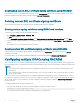
The following table provides information about viewing the sensor information using iDRAC web interface and RACADM. For information
about the properties that are displayed on the web interface, see the iDRAC Online Help.
NOTE
: The Hardware Overview page displays data only for sensors present on your system.
Table 15. Sensor information using web interface and RACADM
View sensor information For Using web interface Using RACADM
Batteries
Overview > Hardware > Batteries
Use the getsensorinfo command.
For power supplies, you can also use the
System.Power.Supply command with the
get subcommand.
108 Viewing iDRAC and managed system information