
White Papers


Table Of Contents
- Executive Summary (updated May 2011)
- 1. Introduction
- 2. Dell NFS Storage Solution Technical Overview
- 3. NFS Storage Solution with High Availability
- 4. Evaluation
- 5. Performance Benchmark Results (updated May 2011)
- 6. Comparison of the NSS Solution Offerings
- 7. Conclusion
- 8. References
- Appendix A: NSS-HA Recipe (updated May 2011)
- A.1. Pre-install preparation
- A.2. Server side hardware set-up
- A.3. Initial software configuration on each PowerEdge R710
- A.4. Performance tuning on the server
- A.5. Storage hardware set-up
- A.6. Storage Configuration
- A.7. NSS HA Cluster setup
- A.8. Quick test of HA set-up
- A.9. Useful commands and references
- A.10. Performance tuning on clients (updated May 2011)
- A.11. Example scripts and configuration files
- Appendix B: Medium to Large Configuration Upgrade
- Appendix C: Benchmarks and Test Tools
Dell HPC NFS Storage Solution - High Availability Configurations
Page 8
Network redundancy
The servers are connected to a Gigabit Ethernet switch that is used as the private network for
communication between the active and passive servers. This network is used to monitor the
heartbeat between the active and passive server. It is also used to communicate to the iDRAC
and power PDUs.
The servers are also connected to an InfiniBand or 10 Gigabit Ethernet network. This is referred
to as the public network. The compute cluster accesses the servers via this network. The public
network switch is outside of the NSS-HA design. It is assumed that the reliability and
configuration of the public network meets the high availability demands of the cluster. A single
network card failure in one NFS server can be tolerated since there is a second server with an
equivalent data path to the clients.
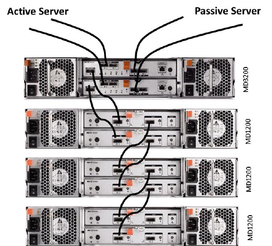
Disk redundancy
The storage for user data consists of a PowerVault MD3200 enclosure and one or more
PowerVault MD1200 expansion arrays. Each array contains twelve 3.5” 2TB 7200rpm NearLine
SAS disks. The disks in each array are set up in RAID 6, 10+2 configuration with 10 data disks
and two parity disks. Such a RAID configuration provides sufficient redundancy to rebuild data
when there is a disk failure. The segment size of each virtual disk is 512k. This gives each
storage array a capacity of 20TB (10 data disks * 2TB per disk) usable space.
The PowerVault MD3200 is configured to have read cache enabled, write cache enabled, write
cache mirroring enabled and read prefetch enabled. The cache block size is set to 32k. Since
the cache mirroring feature is enabled, the two RAID controllers in the MD3200 have mirrored
caches. A single RAID controller failure can be tolerated with no impact to data availability.
Figure 3 - Example of PowerVault Storage Cabling