
Install Guide
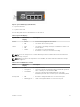


In Stack mode, the lower two external Ethernet ports (ports 9 and 10) operate as stack links. In
Programmable MUX (PMUX) mode, you can configure any of the external Ethernet ports to operate as
stack links.
Assembling a Switch Stack
After you complete the initial configuration, the FN I/O Module is powered up and operational.
FN 410S and FN 410T support two-unit in-chassis stacking and up to six units stacking across chassis.
Cabling the Switch Stack
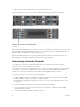
Dell PowerEdge FN I/O Modules are connected to operate as a single stack in a ring topology using the
SFP+ or Base-T ports on the front-end ports 9 and 10. To create a stack in either a ring or daisy-chain
topology, you can use two units on the same chassis or up to six units across multiple chassis.
Prerequisite: Before you attach the stacking cables, all FN I/O Modules in the stack must be powered up
with the default or reconfigured settings.
To connect stacking ports, use only Dell authorized cables (separately purchased). For example:
1. Insert a cable in port 9 on the first FN I/O Module.
2. Connect the cable to port 10 on the next FN I/O Module.
3. Continue this pattern on up to six FN I/O Modules.
4. Connect a cable from port 9 on the last FN I/O Module to port 10 on the first FN I/O Module. It
creates a ring topology.
NOTE: The resulting topology allows the stack to function as a single switch with resilient failover
capabilities.
Programmable MUX Mode
Standalone mode is the zero-touch auto-configuration default mode of the FN I/O Module. If you want
the flexibility to configure different settings, change the FN I/O Module to PMUX mode. PMUX mode
provides additional CLI commands to customize the software configuration as needed.
Full-switch Mode
All the commands and configurations supported on MXL is available in full-switch mode. Full-switch
mode offers Layer 2/ Layer 3 switching functionalities on Dell FX2 chassis.
16
Installation