
Install Guide


• Switch modules: Two FN I/O modules or two pass-through modules.
Install server blades in the front of the chassis; install FN I/O modules in the back of the chassis.
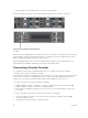
Figure 4. Front View with Server Modules
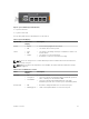
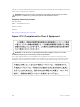
Figure 5. Back View with Two FN I/O Modules
1 — CMC
After you slide the FN I/O Module in so that the connectors on the back of the blade are inserted into the
chassis midplane, the switch automatically powers on. The CMC in the chassis validates that the switch
blade is a supported FN I/O module before powering it on.
When the FN I/O Module powers on, the bootloader loads the image in the local flash memory. The
image initializes the hardware and brings up the switch in operational mode.
Connecting a Console Terminal
To configure the switch, after the FN I/O Module powers on, complete all the external cabling
connections and connect a terminal to the switch.
To monitor and configure the switch with the serial console, use the USB console port on the front panel
of the switch to connect it to a VT100 terminal or to a computer running VT100 terminal emulation
software. The console port is implemented as a data terminal equipment (DTE) connector.
To use the console port, you need the following equipment:
• VT100-compatible terminal, or a desktop, or a laptop computer with a serial port running VT100
terminal emulation software, such as Microsoft HyperTerminal.
• A serial cable (provided) with a USB type-A connector for the console port and DB-9 connector for
the terminal.
To connect a terminal to the switch console port, perform the following tasks:
1. Connect the DB-9 connector on the serial cable to the terminal or computer running VT100
terminal emulation software.
2. Configure the terminal emulation software as follows:
14
Installation