
Deployment Guide


EXEC mode
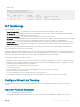
Dell# show interfaces port brief
Codes: L - LACP Port-channel
O - OpenFlow Controller Port-channel
LAG Mode Status Uptime Ports
127 L2 up 00:18:22 Fo 0/33 (Up)<<<<<<<<ICL LAG
Fo 0/37 (Up)
L 128 L2 up 00:00:00 Fo 0/41 (Up)<<<<<<<<Uplink LAG
VLT Terminology
The following are key VLT terms.
• Virtual link trunk (VLT) — The combined port channel between an attached device and the VLT peer switches.
• VLT backup link — The backup link monitors the connectivity between the VLT peer switches. The backup link sends congurable,
periodic keep alive messages between the VLT peer switches.
• VLT interconnect (VLTi) — The link used to synchronize states between the VLT peer switches.
• VLT domain — This domain includes both the VLT peer devices, VLT interconnect, and all of the port channels in the VLT connected to
the attached devices. It is also associated to the conguration mode that you must use to assign VLT global parameters.
• VLT peer device — One of a pair of devices that are connected with the special port channel known as the VLT interconnect (VLTi).
• Enhanced VLT (eVLT) — Combining two VLT domains. eVLT can operate in layer 2 and layer 3 modes. eVLT is also known as mVLT.
VLT peer switches have independent management planes. A VLT interconnect between the VLT chassis maintains synchronization of
L2/L3 control planes across the two VLT peer switches.
A separate backup link maintains heartbeat messages across an out-of-band (OOB) management network. The backup link ensures that
node failure conditions are correctly detected and are not confused with failures of the VLT interconnect. VLT ensures that local trac on a
chassis does not traverse the VLTi and takes the shortest path to the destination via directly attached links.
The following is a summary of VLT and its functions:
• End devices (such as switches, servers, and so on) connected to a VLT domain consider the two VLT peers as a single logical switch.
• Although VLT does not require spanning tree protocols, Dell Networking recommends enabling RSTP before conguring VLT to avoid
possible loops from forming due to incorrect conguration.
• You can connect two VLT domains to create an eVLT topology.
• You can use eVLT as layer 2.
• Peer routing enables one VLT node to act as the default gateway for its VLT peer within a VLT domain.
• With peer routing, you need not use VRRP.
• You can use routing protocols in a VLT domain or between VLT domains (eVLT).
• VLT Proxy Gateway enables one VLT domain to act as the default gateway for its peer VLT domain in an eVLT topology.
Congure Virtual Link Trunking
VLT requires that you enable the feature and then congure the same VLT domain, backup link, and VLT interconnect on both peer
switches.
Important Points to Remember
• VLT port channel interfaces must be switch ports.
• Dell Networking strongly recommends that the VLTi (VLT interconnect) be a static LAG and that you disable LACP on the VLTi.
PMUX Mode of the IO Aggregator
827