
Deployment Guide


STP Root Guard
Use the STP root guard feature in a Layer 2 network to avoid bridging loops.
In STP, the switch in the network with the lowest priority (as determined by STP or set with the bridge-priority command) is
selected as the root bridge. If two switches have the same priority, the switch with the lower MAC address is selected as the root. All other
switches in the network use the root bridge as the reference used to calculate the shortest forwarding path.
Because any switch in an STP network with a lower priority can become the root bridge, the forwarding topology may not be stable. The
location of the root bridge can change, resulting in unpredictable network behavior. The STP root guard feature ensures that the position of
the root bridge does not change.
Root Guard Scenario
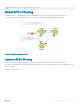
For example, as shown in the following illustration (STP topology 1, upper left) Switch A is the root bridge in the network core. Switch C
functions as an access switch connected to an external device. The link between Switch C and Switch B is in a Blocking state. The ow of
STP BPDUs is shown in the illustration.
In STP topology 2 (shown in the upper right), STP is enabled on device D on which a software bridge application is started to connect to
the network. Because the priority of the bridge in device D is lower than the root bridge in Switch A, device D is elected as root, causing
the link between Switches A and B to enter a Blocking state. Network trac then begins to ow in the directions indicated by the BPDU
arrows in the topology. If the links between Switches C and A or Switches C and B cannot handle the increased trac ow, frames may be
dropped.
In STP topology 3 (shown in the lower middle), if you have enabled the root guard feature on the STP port on Switch C that connects to
device D, and device D sends a superior BPDU that would trigger the election of device D as the new root bridge, the BPDU is ignored and
the port on Switch C transitions from a forwarding to a root-inconsistent state (shown by the green X icon). As a result, Switch A becomes
the root bridge.
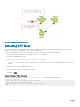
All incoming and outgoing trac is blocked on an STP port in a Root-Inconsistent state. After the timeout period, the Switch C port
automatically transitions to a Forwarding state as soon as device D stops sending BPDUs that advertise a lower priority.
If you enable a root guard on all STP ports on the links where the root bridge should not appear, you can ensure a stable STP network
topology and avoid bridging loops.
Spanning Tree Protocol (STP)
795