
Deployment Guide
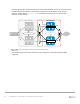


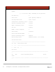
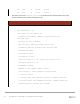


Table Of Contents
- 1 Introduction
- 2 The Dell FX2 and FN I/O Modules
- 3 Initial out-of-box connectivity check and default settings
- 4 VLT and the example environments
- 5 FN IOM Dell Blade I/O manager and internal port mapping features
- 6 Environment One: Basic VLT deployment with VLT mode
- 7 Environment Two: Dell Networking switches with mVLT and IOM in Full Switch mode
- 8 Environment Three: Dell Networking switches with mVLT and FN IOM in programmable MUX mode.
- 9 Environment Four: VLT interoperability with Cisco vPC
- A References
- B Components
- C Terminology
- D Reset FN IOM to Default Factory Configuration
- E FN IOM initial out-of-box configuration and default settings
- F Support and feedback
81 PowerEdge FX2 – FN I/O Module – VLT Deployment Guide | Version 2.2
Once the vPC domain is created, the vPC Peer-Link is formed using port channel 55. The port channel
connects both vPC peer switches and should be configured to carry all VLANs. Finally, the port
channel is enabled and the vpc peer link command is issued to specify the role of this port
channel in the vPC domain.
VLT Domain vPC Domain
FC630 Server
Peer Link
VLTi
FN410S-A1
FN410S-A2
Nx5672-2
Nx5672-1
E 1/2
E 1/2
E 1/1
E 1/1
E 1/24
E 1/24
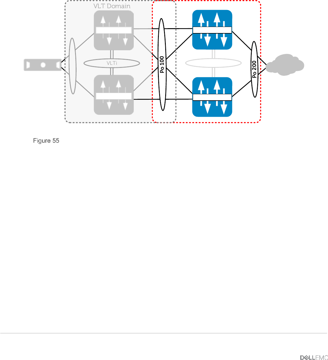
Nexus virtual port channels and vPC member ports
The virtual port channels and vPC member ports are configured for connectivity to the FN IOM’s
(Figure 55).