
Deployment Guide
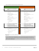


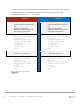
Table Of Contents
- 1 Introduction
- 2 The Dell FX2 and FN I/O Modules
- 3 Initial out-of-box connectivity check and default settings
- 4 VLT and the example environments
- 5 FN IOM Dell Blade I/O manager and internal port mapping features
- 6 Environment One: Basic VLT deployment with VLT mode
- 7 Environment Two: Dell Networking switches with mVLT and IOM in Full Switch mode
- 8 Environment Three: Dell Networking switches with mVLT and FN IOM in programmable MUX mode.
- 9 Environment Four: VLT interoperability with Cisco vPC
- A References
- B Components
- C Terminology
- D Reset FN IOM to Default Factory Configuration
- E FN IOM initial out-of-box configuration and default settings
- F Support and feedback
79 PowerEdge FX2 – FN I/O Module – VLT Deployment Guide | Version 2.2
Figure 53 presents the steps to configure the vPC domain.
Nx5672-1
Nx5672-2
Enable the features and
management interface for vPC
Enable LACP and vPC features
Enable the features and
management interface for vPC
Enable LACP and vPC features
configure
feature lacp
feature vpc
configure
feature lacp
feature vpc
Assign an IP address to
management interface
Assign an IP address to
management interface
interface mgmt 0
ip address
172.25.109.37/16
no shutdown
exit
interface mgmt 0
ip address
172.25.109.24/16
no shutdown
exit
Create the VPC domain
Assign a role priority of 1
Assign the keepalive management
IP of Switch A2
Create the VPC domain
Assign a role priority of 65535
Assign the keepalive management
IP of Switch A1
vpc domain 1
role priority 1
peer-keepalive dest
172.25.109.24
exit
vpc domain 1
role priority 65535
peer-keepalive dest
172.25.109.37
exit
vPC domain and initial configuration
The role priority 1 command specifies that Switch Nx5672-1 will be the primary switch in the
vPC domain. On the other switch, a role priority of 65535 will be used to ensure the roles will be
assigned properly if the switches are rebooted. Finally, a peer keepalive address is specified. The peer
keepalive address is the management address of the vPC peer switch. This setting allows keepalive
heartbeat packets to flow through the management network.