
Deployment Guide
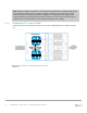
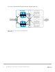


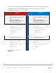
Table Of Contents
- 1 Introduction
- 2 The Dell FX2 and FN I/O Modules
- 3 Initial out-of-box connectivity check and default settings
- 4 VLT and the example environments
- 5 FN IOM Dell Blade I/O manager and internal port mapping features
- 6 Environment One: Basic VLT deployment with VLT mode
- 7 Environment Two: Dell Networking switches with mVLT and IOM in Full Switch mode
- 8 Environment Three: Dell Networking switches with mVLT and FN IOM in programmable MUX mode.
- 9 Environment Four: VLT interoperability with Cisco vPC
- A References
- B Components
- C Terminology
- D Reset FN IOM to Default Factory Configuration
- E FN IOM initial out-of-box configuration and default settings
- F Support and feedback
77 PowerEdge FX2 – FN I/O Module – VLT Deployment Guide | Version 2.2
Figure 51 shows that the Dell Networking architecture for mVLT is very similar to this brand-varied
Multi-Chassis Link Aggregation Group (MC-LAG) architecture.
VLT Domain vPC Domain
Peer Link
VLTi
FN IOM
FN IOM
Nexus 5000
Nexus 5000
FC630 Server
Cisco vPC – Dell Networking VLT – multi-vendor same port channels
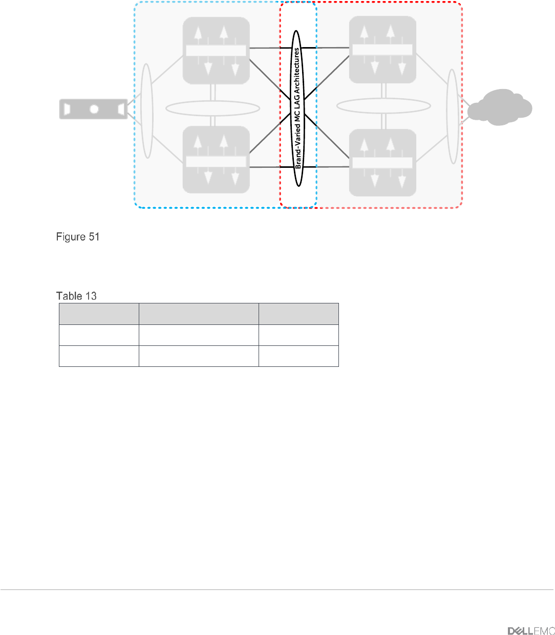
The configuration steps outlined below are repeated on both Nexus switches. When validating the
configurations in this guide the following management IP addresses (Table 13) were used.
IP Addresses
Hostname
IP Address
Subnet
Nx5672-1
172.25.109.37
255.255.0.0
Nx5672-2
172.25.109.24
255.255.0.0