
Deployment Guide
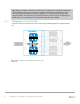
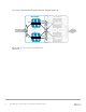


Table Of Contents
- 1 Introduction
- 2 The Dell FX2 and FN I/O Modules
- 3 Initial out-of-box connectivity check and default settings
- 4 VLT and the example environments
- 5 FN IOM Dell Blade I/O manager and internal port mapping features
- 6 Environment One: Basic VLT deployment with VLT mode
- 7 Environment Two: Dell Networking switches with mVLT and IOM in Full Switch mode
- 8 Environment Three: Dell Networking switches with mVLT and FN IOM in programmable MUX mode.
- 9 Environment Four: VLT interoperability with Cisco vPC
- A References
- B Components
- C Terminology
- D Reset FN IOM to Default Factory Configuration
- E FN IOM initial out-of-box configuration and default settings
- F Support and feedback
76 PowerEdge FX2 – FN I/O Module – VLT Deployment Guide | Version 2.2
port-channel 128 mode
active
exit
no shutdown
exit
port-channel 128 mode
active
exit
no shutdown
exit
Configuring VLT member ports to downstream servers and uplinked Cisco Nexus
9.2 Environment Four: Cisco Nexus 5000 Series vPC configuration
In this section, vPC is configured on the Cisco Nexus 5672 (Figure 51 thru Figure 57).
Note: The following vPC configuration is based on recommendations from: Cisco NX-OS Software
Virtual PortChannel: Fundamental Concepts 5.0 (Cisco Inc.).
A single vPC domain with the following critical components is required for a successful vPC
deployment:
vPC Peer Switches: Two switches connected using a special port channel known as a vPC
Peer-Link.
vPC Peer Link: This port channel is used to synchronize data between the vPC peer
switches. The link carrier controls traffic between two vPC switches as well as multicast and
broadcast data.
vPC Domain: A vPC domain contains both vPC peer switches, the vPC peer keepalive link
and all of the port channels in the vPC connected to the downstream devices. A domain can
be assigned with a value from 1 to 1000.
vPC Peer Keepalive Link: The keepalive link monitors the vitality of a vPC peer switch. This
link will send periodic keepalive messages between vPC peer switches. This link can be part
of the management network, as it does not send data or synchronization traffic, only keepalive
messages.
vPC Member Ports: vPC member ports are interfaces that belong to the vPCs.
Note: A full list of terms can be found in the Terminology section of the Appendix.