
Deployment Guide
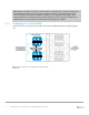
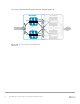


Table Of Contents
- 1 Introduction
- 2 The Dell FX2 and FN I/O Modules
- 3 Initial out-of-box connectivity check and default settings
- 4 VLT and the example environments
- 5 FN IOM Dell Blade I/O manager and internal port mapping features
- 6 Environment One: Basic VLT deployment with VLT mode
- 7 Environment Two: Dell Networking switches with mVLT and IOM in Full Switch mode
- 8 Environment Three: Dell Networking switches with mVLT and FN IOM in programmable MUX mode.
- 9 Environment Four: VLT interoperability with Cisco vPC
- A References
- B Components
- C Terminology
- D Reset FN IOM to Default Factory Configuration
- E FN IOM initial out-of-box configuration and default settings
- F Support and feedback
73 PowerEdge FX2 – FN I/O Module – VLT Deployment Guide | Version 2.2
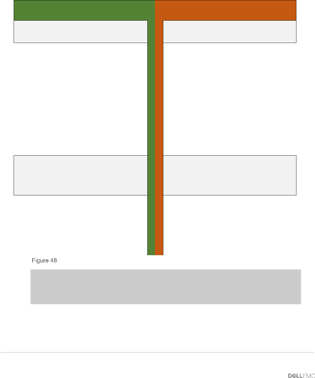
Figure 48 contains the steps necessary to configure the VLTi.
FN410S-A1
FN410S-A2
Configure the VLTi and member
links
Configure the VLTi and member
links
interface Port-channel 127
description "VLTi LAG to
FN410S-A2"
channel-member
TenGigabitEthernet 0/9-10
no shutdown
exit
interface range
TenGigabitEthernet 0/9-10
description "Link to
FN410S-A2"
no switchport
no shutdown
exit
interface Port-channel 127
description "VLTi LAG to
FN410S-A2"
channel-member
TenGigabitEthernet 0/9-10
no shutdown
exit
interface range
TenGigabitEthernet 0/9-10
description "Link to
FN410S-A2"
no switchport
no shutdown
exit
Configure the VLT domain and set
the peer link port channel
Configure the backup destination
(management IP of the other switch)
Configure the VLT domain and set
the peer link port channel
Configure the backup destination
(management IP of the other switch)
vlt domain 1
peer-link port-channel
127
back-up destination
172.25.210.56
unit-id 0
exit
vlt domain 1
peer-link port-channel
127
back-up destination
172.25.210.55
unit-id 1
exit
IOM VLT peer link configuration
Note: When you create a VLT domain on a switch, the system automatically assigns a unique unit ID
(0 or 1) to each peer switch. Optionally, the unit ID can be manually configured as shown above to
minimize the time required for the VLT system to determine the unit ID assigned to each peer switch
when one peer switch reboots.