
Deployment Guide
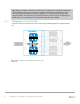
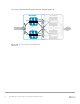


Table Of Contents
- 1 Introduction
- 2 The Dell FX2 and FN I/O Modules
- 3 Initial out-of-box connectivity check and default settings
- 4 VLT and the example environments
- 5 FN IOM Dell Blade I/O manager and internal port mapping features
- 6 Environment One: Basic VLT deployment with VLT mode
- 7 Environment Two: Dell Networking switches with mVLT and IOM in Full Switch mode
- 8 Environment Three: Dell Networking switches with mVLT and FN IOM in programmable MUX mode.
- 9 Environment Four: VLT interoperability with Cisco vPC
- A References
- B Components
- C Terminology
- D Reset FN IOM to Default Factory Configuration
- E FN IOM initial out-of-box configuration and default settings
- F Support and feedback
72 PowerEdge FX2 – FN I/O Module – VLT Deployment Guide | Version 2.2
Note: When an FN IOM is connected to a Cisco Nexus in the default state, a number of DCBX (Data
Center Bridging Exchange) error messages are logged and shown on the FN IOM serial console
each time a port or port channel is shutdown or brought up. To suppress these messages, either
configure DCBX on the FN IOM and Nexus switches (which is out of the scope of this document) or
disable DCB on the FN IOM with the command: Dell(conf)#no dcb enable
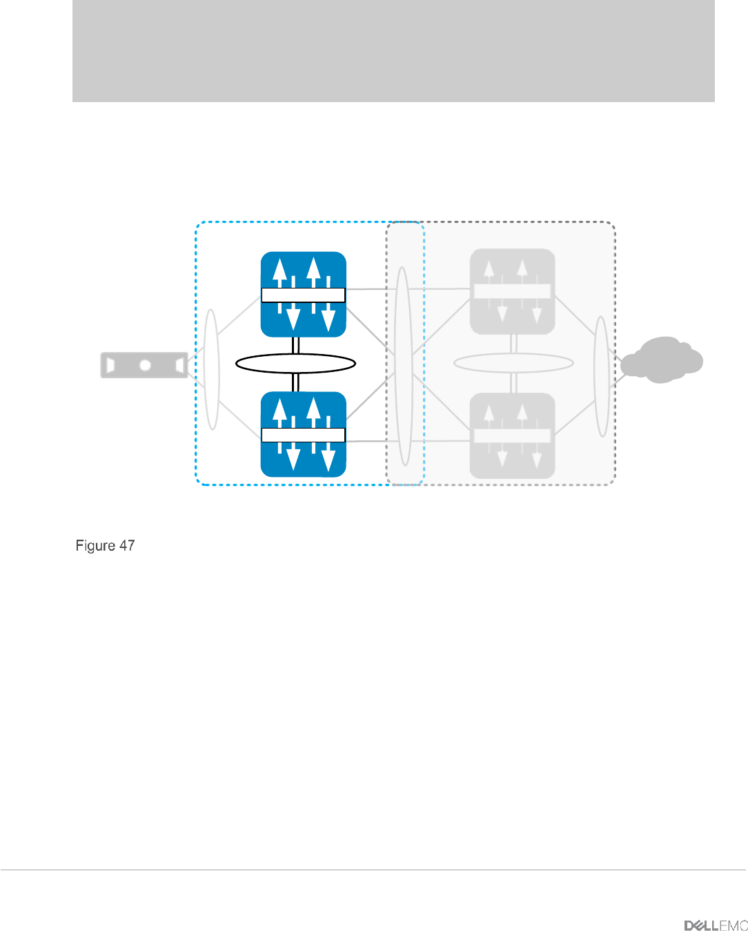
9.1.2 Configuring VLT on the FN IOM
In this section, the VLT domain and VLTi (VLT interconnect) participating links are configured (Figure
47).
VLT Domain vPC Domain
VLTi (Po 127)
Te 0/10Te 0/9
Nx5672-1
Nx5672-2
FN410S-A1
FN410S-A2
Te 0/9 Te 0/10
FC630 Server
FN410S VLT Configuration and VLTi setup