
Deployment Guide


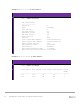

Table Of Contents
- 1 Introduction
- 2 The Dell FX2 and FN I/O Modules
- 3 Initial out-of-box connectivity check and default settings
- 4 VLT and the example environments
- 5 FN IOM Dell Blade I/O manager and internal port mapping features
- 6 Environment One: Basic VLT deployment with VLT mode
- 7 Environment Two: Dell Networking switches with mVLT and IOM in Full Switch mode
- 8 Environment Three: Dell Networking switches with mVLT and FN IOM in programmable MUX mode.
- 9 Environment Four: VLT interoperability with Cisco vPC
- A References
- B Components
- C Terminology
- D Reset FN IOM to Default Factory Configuration
- E FN IOM initial out-of-box configuration and default settings
- F Support and feedback
61 PowerEdge FX2 – FN I/O Module – VLT Deployment Guide | Version 2.2
no shutdown
exit
interface range te0/1-2
description “Portchannel
link to IOM”
no switchport
port-channel-protocol lacp
port-channel 121 mode
active
exit
no shutdown
no shutdown
exit
interface range te0/1-
2
description
“Portchannel link to
IOM”
no switchport
port-channel-protocol
lacp
port-channel 121 mode
active
exit
no shutdown
S4810 VLT configuration
Note: When you create a VLT domain on a switch, the system automatically assigns a unique unit ID
(0 or 1) to each peer switch. Optionally, the unit ID can be manually configured as shown in the
examples above to minimize the time required for the VLT system to determine the unit ID assigned
to each peer switch when one peer switch reboots.
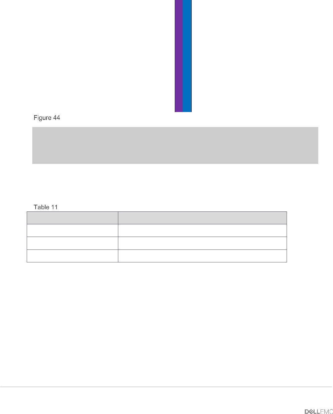
8.3 Environment Three: Verifying VLT Connectivity
VLT connectivity can be checked using the VLT commands listed in Table 11.
show commands
Command
Purpose
show vlt brief
Displays brief information about the VLT configuration
show vlt detail
Displays running configuration for VLT members
show mac-address-table
Displays the MAC address table
On each switch participating in VLT, perform a show vlt brief, show vlt detail and show
mac-address-table. On the access switch, perform a show mac-address-table.
show vlt brief
The Role (Primary or Secondary) should be appropriate for the switch. The status of the ICL Link,
HeartBeat and VLT Peer must all be up.
show vlt detail
This command shows the local LAG ID, the peer LAG ID, the local status of the VLT, the peer status of
the VLT, and the active VLANs for the VLT.
Columns Local Status and Peer status must be UP in order for the LAG to be functional.