
Deployment Guide
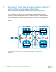
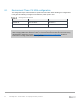
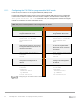
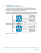

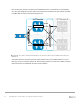
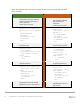


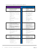
Table Of Contents
- 1 Introduction
- 2 The Dell FX2 and FN I/O Modules
- 3 Initial out-of-box connectivity check and default settings
- 4 VLT and the example environments
- 5 FN IOM Dell Blade I/O manager and internal port mapping features
- 6 Environment One: Basic VLT deployment with VLT mode
- 7 Environment Two: Dell Networking switches with mVLT and IOM in Full Switch mode
- 8 Environment Three: Dell Networking switches with mVLT and FN IOM in programmable MUX mode.
- 9 Environment Four: VLT interoperability with Cisco vPC
- A References
- B Components
- C Terminology
- D Reset FN IOM to Default Factory Configuration
- E FN IOM initial out-of-box configuration and default settings
- F Support and feedback
58 PowerEdge FX2 – FN I/O Module – VLT Deployment Guide | Version 2.2
interface range te0/11-12
description “Link to Dell
S4810”
no switchport
port-channel-protocol lacp
port-channel 121 mode
active
exit
no shutdown
exit
interface range
te0/11-12
description “Link to
Dell S4810”
no switchport
port-channel-
protocol lacp
port-channel 121
mode active
exit
no shutdown
exit
Connection to Server NICs and Connections to S4810 Switches
8.2 Environment Three: Configuring the Dell Networking S4810
In this section, the S4810 switches are configured (Figure 43). The configuration steps outlined below
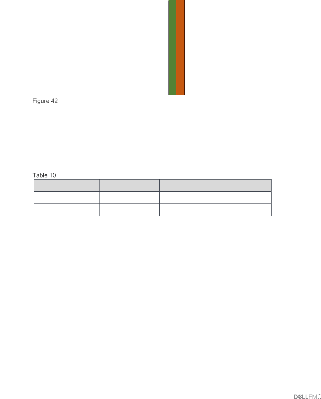
are repeated on both IOMs. When validating the configurations in this guide the following management
IP addresses (Table 10) were used.
Management IP addresses
Hostname
IP Address
Subnet
S4810-1
172.25.190.37
255.255.0.0
S4810-2
172.25.190.38
255.255.0.0
The VLT active/active capabilities of the S4810 and the IOM are the same. Therefore, the
configurations should look and behave in the same manner.