
Deployment Guide
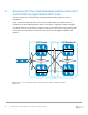
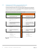
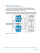

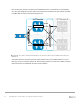
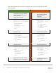


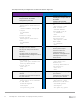
Table Of Contents
- 1 Introduction
- 2 The Dell FX2 and FN I/O Modules
- 3 Initial out-of-box connectivity check and default settings
- 4 VLT and the example environments
- 5 FN IOM Dell Blade I/O manager and internal port mapping features
- 6 Environment One: Basic VLT deployment with VLT mode
- 7 Environment Two: Dell Networking switches with mVLT and IOM in Full Switch mode
- 8 Environment Three: Dell Networking switches with mVLT and FN IOM in programmable MUX mode.
- 9 Environment Four: VLT interoperability with Cisco vPC
- A References
- B Components
- C Terminology
- D Reset FN IOM to Default Factory Configuration
- E FN IOM initial out-of-box configuration and default settings
- F Support and feedback
57 PowerEdge FX2 – FN I/O Module – VLT Deployment Guide | Version 2.2
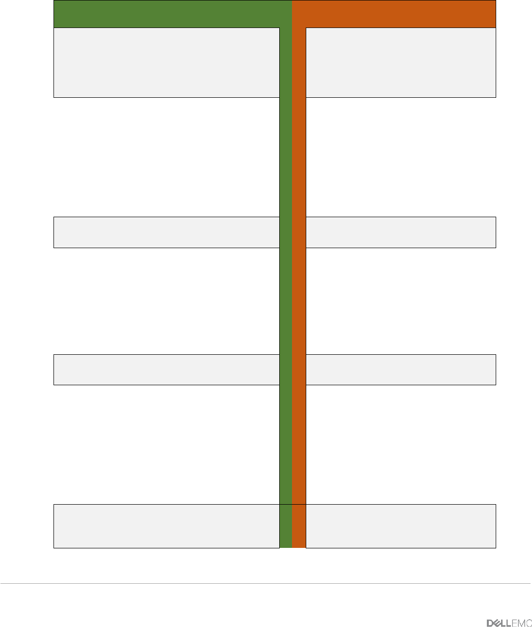
Figure 42 contains the steps necessary to configure the peer LAG and the upstream links for the
mVLT connection.
FN410S-A1
FN410S-A2
Configure the peer LAG, and then
configure upstream links for the
mVLT connection.
Create the port channel
Configure the peer LAG, and
then configure upstream
links for the mVLT
connection.
Create the port channel
interface port-channel 101
description “PO to CNA NIC
1”
portmode hybrid
switchport
vlt-peer-lag po101
no shutdown
exit
interface port-
channel 101
description “PO to
CNA NIC 1”
portmode hybrid
switchport
vlt-peer-lag po101
no shutdown
exit
Configure the internal port and set
the port channel
Configure the internal port
and set the port channel
interface te0/1
no switchport
port-channel-protocol lacp
port-channel 101 mode
active
no shutdown
exit
interface te0/1
no switchport
port-channel-
protocol lacp
port-channel 101
mode active
no shutdown
exit
Configure the port channel for
upstream interfaces
Configure the port channel
for upstream interfaces
interface port-channel 121
description “PO to Dell
S4810”
portmode hybrid
switchport
vlt-peer-lag po121
no shutdown
exit
interface port-
channel 121
description “PO to
Dell S4810”
portmode hybrid
switchport
vlt-peer-lag po121
no shutdown
exit
Configure the interfaces that will
participate in the VLT port channel.
Configure the interfaces that
will participate in the VLT
port channel.