
Deployment Guide
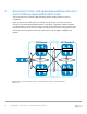
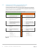
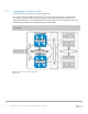

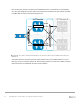
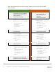


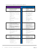
Table Of Contents
- 1 Introduction
- 2 The Dell FX2 and FN I/O Modules
- 3 Initial out-of-box connectivity check and default settings
- 4 VLT and the example environments
- 5 FN IOM Dell Blade I/O manager and internal port mapping features
- 6 Environment One: Basic VLT deployment with VLT mode
- 7 Environment Two: Dell Networking switches with mVLT and IOM in Full Switch mode
- 8 Environment Three: Dell Networking switches with mVLT and FN IOM in programmable MUX mode.
- 9 Environment Four: VLT interoperability with Cisco vPC
- A References
- B Components
- C Terminology
- D Reset FN IOM to Default Factory Configuration
- E FN IOM initial out-of-box configuration and default settings
- F Support and feedback
55 PowerEdge FX2 – FN I/O Module – VLT Deployment Guide | Version 2.2
Figure 40 contains the steps necessary to configure the VLT peer links.
FN410S- A1
FN410S- A2
Configure the VLTi Port-Channel
interface
Add a description
Add channel members
Configure the VLTi Port-
Channel interface
Add a description
Add channel members
interface port-channel 127
description VLTI link to
VLT- Switch A2
channel-member te0/9 – 10
no switchport
no shutdown
exit
interface port-channel
127
description VLTI
link to VLT- Switch A1
channel-member te0/9 –
10
no switchport
no shutdown
exit
Configure the VLT domain
Set peer link port channel of Switch
A2
Configure the backup destination
management IP (management IP of
the other switch)
Set unit id
Configure the VLT domain
Set peer link port channel of
Switch A1
Configure the backup
destination management IP
(management IP of the other
switch)
Set unit id
vlt domain 1
peer-link port-channel
127
back-up destination
172.25.189.28
unit-id 0
exit
vlt domain 1
peer-link port-
channel 127
back-up destination
172.25.189.27
unit-id 1
exit
Configuring the VLT participating links