
Deployment Guide
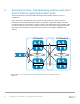
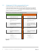
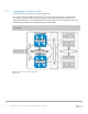

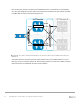


Table Of Contents
- 1 Introduction
- 2 The Dell FX2 and FN I/O Modules
- 3 Initial out-of-box connectivity check and default settings
- 4 VLT and the example environments
- 5 FN IOM Dell Blade I/O manager and internal port mapping features
- 6 Environment One: Basic VLT deployment with VLT mode
- 7 Environment Two: Dell Networking switches with mVLT and IOM in Full Switch mode
- 8 Environment Three: Dell Networking switches with mVLT and FN IOM in programmable MUX mode.
- 9 Environment Four: VLT interoperability with Cisco vPC
- A References
- B Components
- C Terminology
- D Reset FN IOM to Default Factory Configuration
- E FN IOM initial out-of-box configuration and default settings
- F Support and feedback
54 PowerEdge FX2 – FN I/O Module – VLT Deployment Guide | Version 2.2
8.1.2 Configuring VLT on the FN IOM
In this section, the VLTi peer link is configured (Figure 39).
First, the port channel that will be assigned as the VLTi peer link is created. Next, in PMUX mode, a
VLT domain is created. The peer link is then assigned and the backup destination is configured to
enable the heartbeats to go over the management network. Finally, a unit ID is specified to ensure that
the two IOM peer switches are assigned primary or secondary roles.
Note: In this example, the port channel number matches on both sides. This is not a strict
requirement.
VLT Domain VLT Domain 2
VLTi (Po 127)
FC630 Server
Te 0/9 Te 0/10
FN410S-A1
FN410S-A2
S4810-1
Te 0/10Te 0/9
S4810-2
VLTi peer link configuration