
Deployment Guide
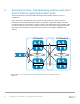

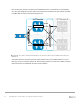


Table Of Contents
- 1 Introduction
- 2 The Dell FX2 and FN I/O Modules
- 3 Initial out-of-box connectivity check and default settings
- 4 VLT and the example environments
- 5 FN IOM Dell Blade I/O manager and internal port mapping features
- 6 Environment One: Basic VLT deployment with VLT mode
- 7 Environment Two: Dell Networking switches with mVLT and IOM in Full Switch mode
- 8 Environment Three: Dell Networking switches with mVLT and FN IOM in programmable MUX mode.
- 9 Environment Four: VLT interoperability with Cisco vPC
- A References
- B Components
- C Terminology
- D Reset FN IOM to Default Factory Configuration
- E FN IOM initial out-of-box configuration and default settings
- F Support and feedback
51 PowerEdge FX2 – FN I/O Module – VLT Deployment Guide | Version 2.2
8 Environment Three: Dell Networking switches with mVLT
and FN IOM in programmable MUX mode.
This section presents an example of Dell Networking switches working together in an mVLT
configuration.
Figure 37 illustrates using Dell EMC’s VLT protocol on a pair of IOMs in a switch environment
consisting of two Dell Networking S4810 switches. In this mVLT configuration, multiple valid paths
exist which enable the environment to survive the failure of one S4810 switch and/or one IOM, and/or
one NIC interface per server. Because all paths are actively used, the result is a highly fault-tolerant
environment. This fault-tolerant environment makes full use of the throughput capabilities of all
switches.
VLT Domain VLT Domain 2
S4810-1
S4810-2
VLTi
FC630 Server
FN410S-A1
FN410S-A2
VLTi
mVLT Configuration with a PowerEdge FX2, IOMs and S4810 switches