
Deployment Guide
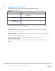
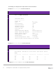
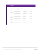


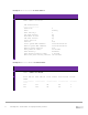


Table Of Contents
- 1 Introduction
- 2 The Dell FX2 and FN I/O Modules
- 3 Initial out-of-box connectivity check and default settings
- 4 VLT and the example environments
- 5 FN IOM Dell Blade I/O manager and internal port mapping features
- 6 Environment One: Basic VLT deployment with VLT mode
- 7 Environment Two: Dell Networking switches with mVLT and IOM in Full Switch mode
- 8 Environment Three: Dell Networking switches with mVLT and FN IOM in programmable MUX mode.
- 9 Environment Four: VLT interoperability with Cisco vPC
- A References
- B Components
- C Terminology
- D Reset FN IOM to Default Factory Configuration
- E FN IOM initial out-of-box configuration and default settings
- F Support and feedback

43 PowerEdge FX2 – FN I/O Module – VLT Deployment Guide | Version 2.2
The following are examples of the output from these show commands.
Example of show vlt brief on switch FN410S-A1.
FN410S-A1
FN410S-A1#show vlt brief
VLT Domain Brief
------------------
Domain ID: 1
Role: Secondary
Role Priority: 32768
ICL Link Status: Up
HeartBeat Status: Up
VLT Peer Status: Up
Local Unit Id: 0
Version: 6(2)
Local System MAC address: 00:1e:c9:de:01:7a
Remote System MAC address: 00:1e:c9:de:01:72
Remote system version: 6(2)
Delay-Restore timer: 90 seconds
Peer-Routing : Disabled
Peer-Routing-Timeout timer: 0 seconds
Multicast peer-routing timeout: 150 seconds
Example of show vlt detail on switch FN410S-A1.
FN410S-A1
FN410S-A1#show vlt detail
Local LAG Id Peer LAG Id Local Status Peer Status Active
VLANs
------------ ----------- ------------ ----------- ---------
----
101 101 UP UP 1
103 104 UP UP 1
121 122 UP UP 1
Example of show mac-address-table on switch FN410S-A1.