
Deployment Guide

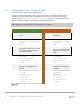


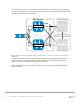


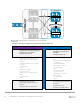
Table Of Contents
- 1 Introduction
- 2 The Dell FX2 and FN I/O Modules
- 3 Initial out-of-box connectivity check and default settings
- 4 VLT and the example environments
- 5 FN IOM Dell Blade I/O manager and internal port mapping features
- 6 Environment One: Basic VLT deployment with VLT mode
- 7 Environment Two: Dell Networking switches with mVLT and IOM in Full Switch mode
- 8 Environment Three: Dell Networking switches with mVLT and FN IOM in programmable MUX mode.
- 9 Environment Four: VLT interoperability with Cisco vPC
- A References
- B Components
- C Terminology
- D Reset FN IOM to Default Factory Configuration
- E FN IOM initial out-of-box configuration and default settings
- F Support and feedback
40 PowerEdge FX2 – FN I/O Module – VLT Deployment Guide | Version 2.2
VLT Domain VLT Domain 2
S4810-1
S4810-2
VLTi (po 55)
FC630 Server
Fo 0/56
Fo 0/56
Fo 0/60
Fo 0/60
FN410S-A1
FN410S-A2
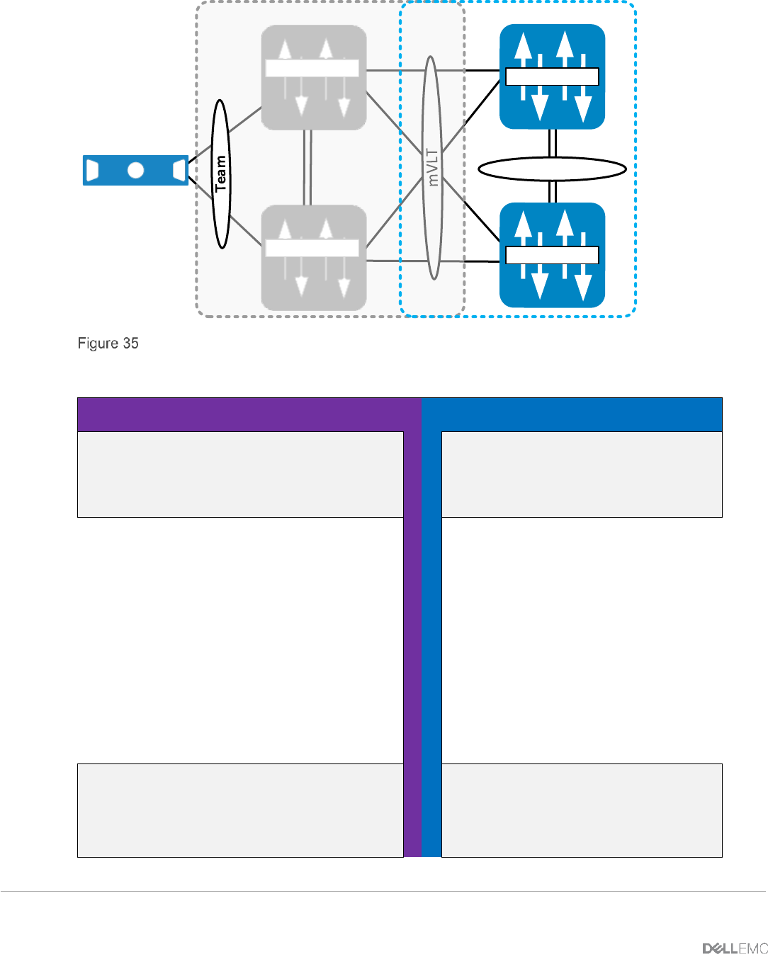
S4810 member and peer link (ICL) configuration
The steps necessary to configure the VLT links are shown in Figure 36.
S4810-1
S4810-2
Configure the VLT links including the
ICL/peer link on the S4810
Configure the peer link
Configure the VLT links
including the ICL/peer link on
the S4810
Configure the peer link
interface port-channel 55
description “VLTi Link to
4810-2”
channel-member fortyGigE
0/56,60
no shutdown
exit
interface range
fo0/56,fo0/60
description “VLTi Peer-
Link”
no shutdown
exit
interface port-channel
55
description “VLTi Link
to 4810-1”
channel-member
fortyGigE 0/56,60
no shutdown
exit
interface range
fo0/56,fo0/60
description “VLTi
Peer-Link”
no shutdown
exit
Configure the VLT domain
Set the peer link port channel of
Switch 2
Configure back-up destination
Configure the VLT domain
Set the peer link port channel
of Switch 1
Configure back-up
destination management IP