
Deployment Guide


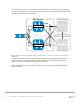


Table Of Contents
- 1 Introduction
- 2 The Dell FX2 and FN I/O Modules
- 3 Initial out-of-box connectivity check and default settings
- 4 VLT and the example environments
- 5 FN IOM Dell Blade I/O manager and internal port mapping features
- 6 Environment One: Basic VLT deployment with VLT mode
- 7 Environment Two: Dell Networking switches with mVLT and IOM in Full Switch mode
- 8 Environment Three: Dell Networking switches with mVLT and FN IOM in programmable MUX mode.
- 9 Environment Four: VLT interoperability with Cisco vPC
- A References
- B Components
- C Terminology
- D Reset FN IOM to Default Factory Configuration
- E FN IOM initial out-of-box configuration and default settings
- F Support and feedback
37 PowerEdge FX2 – FN I/O Module – VLT Deployment Guide | Version 2.2
Next, another port channel is created for the FC630 blade server to communicate. A corresponding
VLT peer lag is assigned to the peer switch. Internal port Te0/1 is added to the port channel and LACP
is enabled with the mode active command.
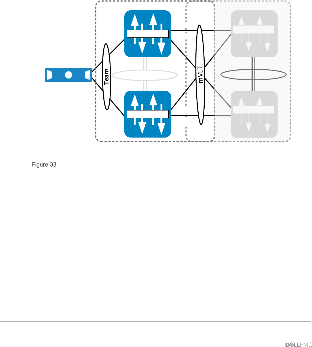
VLT Domain VLT Domain 2
VLTi (Po 127)
FC630 Server
Te 0/9 Te 0/10
Te 0/10Te 0/9
S4810-A2
Te 0/1
Te 0/1
Te 0/11
Te 0/12
FN410S-A1
Te 0/11
S4810-A1
Te 0/12
FN410S-A2
VLT LAG to teamed NIC interfaces (#1) and VLT LAG to mVLT S4810 connection (#2)
A final port channel is created for upstream communication to the pair of S4810 switches. The VLT
peer-lag is set to the same port channel ID. External interfaces 11 and 12 are added to this port
channel and LACP is enabled with the mode active command.
Figure 34 contains the steps necessary to configure the peer LAG and the upstream links for the
mVLT connection.