
Deployment Guide
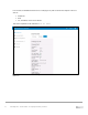
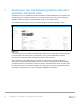


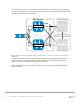


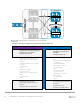
Table Of Contents
- 1 Introduction
- 2 The Dell FX2 and FN I/O Modules
- 3 Initial out-of-box connectivity check and default settings
- 4 VLT and the example environments
- 5 FN IOM Dell Blade I/O manager and internal port mapping features
- 6 Environment One: Basic VLT deployment with VLT mode
- 7 Environment Two: Dell Networking switches with mVLT and IOM in Full Switch mode
- 8 Environment Three: Dell Networking switches with mVLT and FN IOM in programmable MUX mode.
- 9 Environment Four: VLT interoperability with Cisco vPC
- A References
- B Components
- C Terminology
- D Reset FN IOM to Default Factory Configuration
- E FN IOM initial out-of-box configuration and default settings
- F Support and feedback
32 PowerEdge FX2 – FN I/O Module – VLT Deployment Guide | Version 2.2
7 Environment Two: Dell Networking switches with mVLT
and IOM in Full Switch mode
Full Switch mode is a new DNOS 9.10 feature that allows a network administrator to incorporate layer
3 functionality into a FN IOM environment. This new switch mode mirrors the same functionality as
Dell EMC’s award-winning MXL switching module, made for the M1000e chassis.
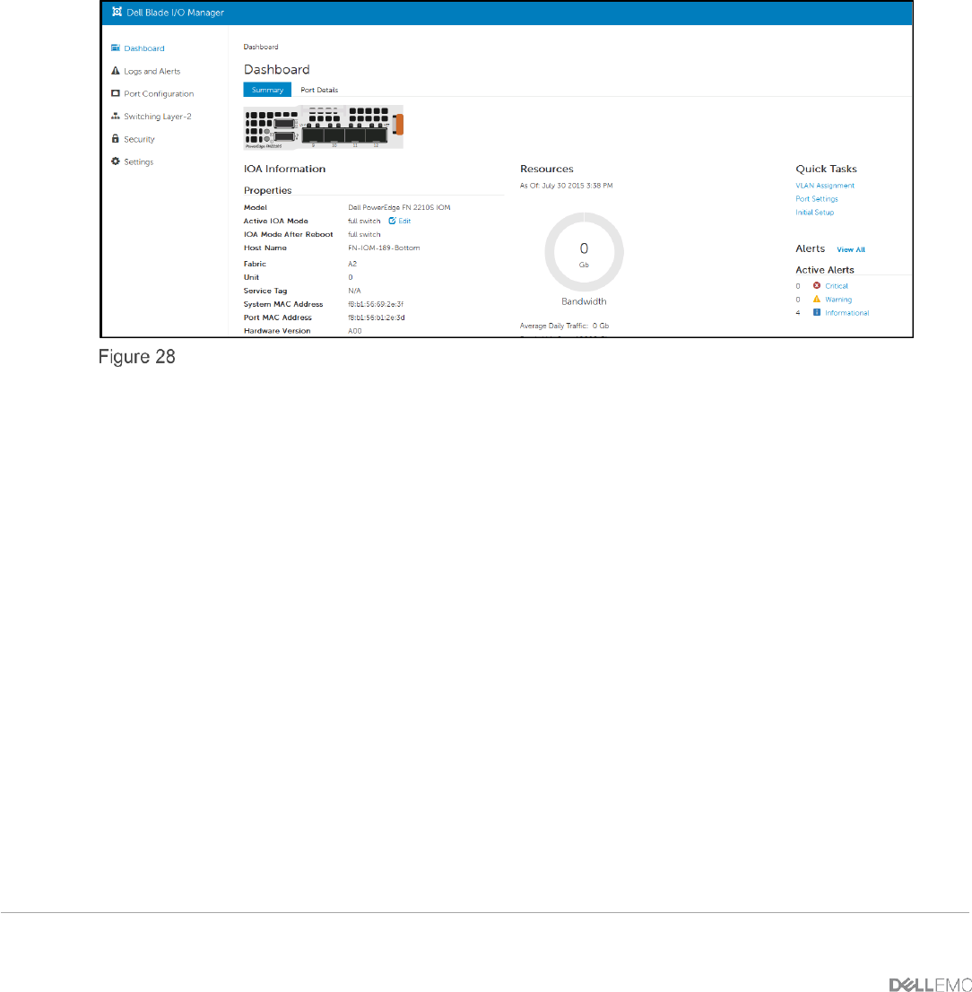
The Dell Blade I/O Manager view (Figure 28) below shows the FN IOM in Full Switch mode.
FN IOM Dell Blade I/O Manager Full Switch mode
This section presents an example of Dell Networking S4810 and FN IOM switches working together
in a multi-Virtual Link Trunking (mVLT) configuration. mVLT represents Dell EMC’s standard
representation of multi-Virtual Link Trunking as presented in this document.
Figure 29 illustrates using Dell EMC’s VLT protocol on a pair of IOMs in a switch environment
connecting to two Dell Networking S4810s switches. In this mVLT configuration, multiple valid paths
exist which enable the environment to survive the failure of one S4810 switch and/or one IOM, and/or
one NIC interface per server. Because all paths are actively used, the result is a highly fault-tolerant
environment, which makes full use of the throughput capabilities of all switches.