
Deployment Guide
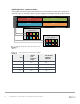
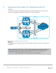
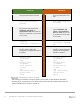
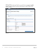
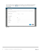
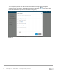
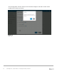
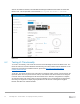
Table Of Contents
- 1 Introduction
- 2 The Dell FX2 and FN I/O Modules
- 3 Initial out-of-box connectivity check and default settings
- 4 VLT and the example environments
- 5 FN IOM Dell Blade I/O manager and internal port mapping features
- 6 Environment One: Basic VLT deployment with VLT mode
- 7 Environment Two: Dell Networking switches with mVLT and IOM in Full Switch mode
- 8 Environment Three: Dell Networking switches with mVLT and FN IOM in programmable MUX mode.
- 9 Environment Four: VLT interoperability with Cisco vPC
- A References
- B Components
- C Terminology
- D Reset FN IOM to Default Factory Configuration
- E FN IOM initial out-of-box configuration and default settings
- F Support and feedback
23 PowerEdge FX2 – FN I/O Module – VLT Deployment Guide | Version 2.2
6.1 Environment One: VLT mode configuration
This configuration requires the IOMs to be changed from the default mode of Standalone to VLT mode.
Figure 20 presents the steps necessary to first verify the current mode of the IOMs, then to change
IOMs to VLT mode. When validating the configurations in this guide the following management IP
addresses (Table 5) were used.
Management IP address
Hostname
IP Address
Subnet
FN410S-A1
172.25.189.27
255.255.0.0
FN410S-A2
172.25.189.28
255.255.0.0
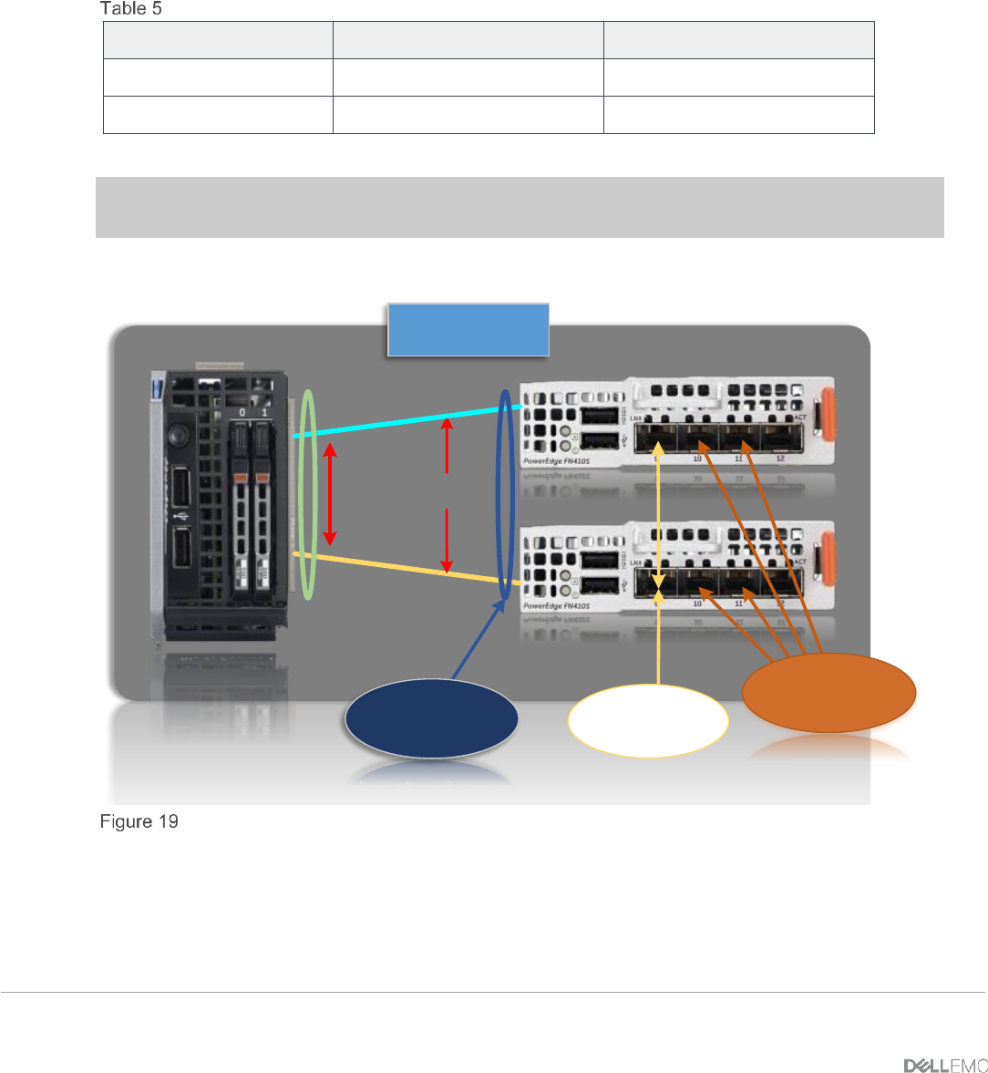
Important: Port Te0/9 is preconfigured for the VLTi peer-link and must be used for this purpose. No
other port may be used for the VLTi peer-link when the IOM is in VLT mode.
NIC Port 1
NIC Port 2
TEAM
Internal
Connections
Te0/1
Te0/1
Blade Server 1
FN410S-A1
FN410S-A2
PowerEdge FX2
Chassis
Internal interfaces
participating in VLT
VLT member/
interfaces
VLTi / ICL peer link
Physical VLT configuration