
Deployment Guide
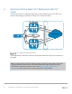
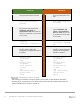
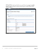
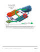
Table Of Contents
- 1 Introduction
- 2 The Dell FX2 and FN I/O Modules
- 3 Initial out-of-box connectivity check and default settings
- 4 VLT and the example environments
- 5 FN IOM Dell Blade I/O manager and internal port mapping features
- 6 Environment One: Basic VLT deployment with VLT mode
- 7 Environment Two: Dell Networking switches with mVLT and IOM in Full Switch mode
- 8 Environment Three: Dell Networking switches with mVLT and FN IOM in programmable MUX mode.
- 9 Environment Four: VLT interoperability with Cisco vPC
- A References
- B Components
- C Terminology
- D Reset FN IOM to Default Factory Configuration
- E FN IOM initial out-of-box configuration and default settings
- F Support and feedback
22 PowerEdge FX2 – FN I/O Module – VLT Deployment Guide | Version 2.2
6 Environment One: Basic VLT deployment with VLT
mode
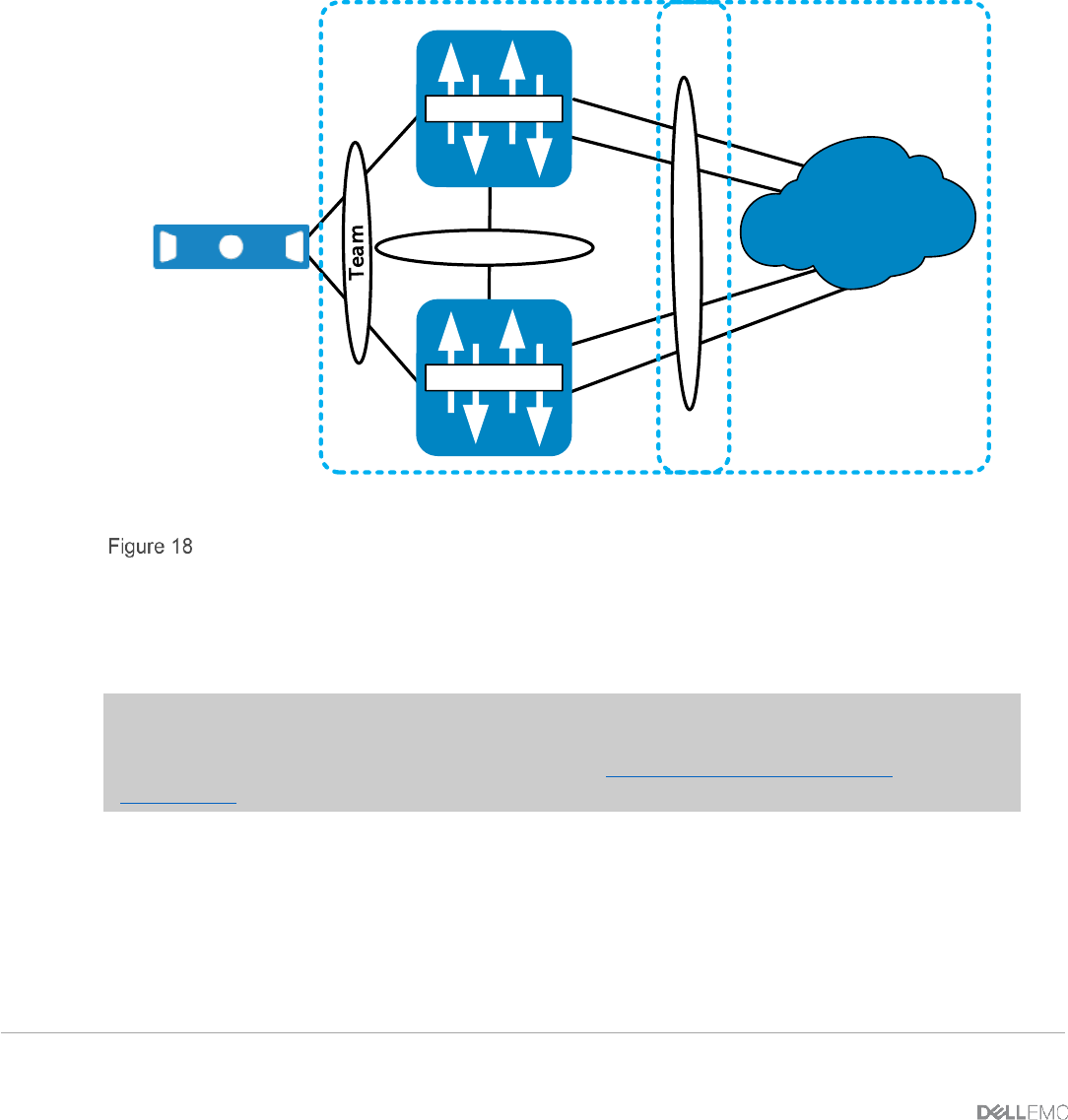
In this section, a basic VLT deployment (Figure 18) is created using the low-touch VLT mode. The
purpose of this topology is to present the concept of VLT and how to enable it.
VLT Domain
VLTi
FC630 Server
FN IOM
FN IOM
Infrastructure
Te 0/9
Te 0/11
Te 0/11
Te 0/1
Te 0/1
Te 0/9
Te 0/10
Te 0/10
VLT deployment with FN 410S IOM
In the diagram above, internal port Te0/1 and external ports Te0/10 and Te0/11 are VLT members on
both IOMs.
Note: If an IOM has been previously configured, existing configuration settings will be retained after
changing IOM modes. Because of this, it is recommended that the IOMs be returned to factory
defaults before configuring to a different mode. See the Reset FN IOM to Default Factory
Configuration section for instructions on setting an IOM back to factory defaults.