
Deployment Guide
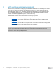
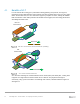

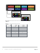
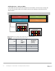
Table Of Contents
- 1 Introduction
- 2 The Dell FX2 and FN I/O Modules
- 3 Initial out-of-box connectivity check and default settings
- 4 VLT and the example environments
- 5 FN IOM Dell Blade I/O manager and internal port mapping features
- 6 Environment One: Basic VLT deployment with VLT mode
- 7 Environment Two: Dell Networking switches with mVLT and IOM in Full Switch mode
- 8 Environment Three: Dell Networking switches with mVLT and FN IOM in programmable MUX mode.
- 9 Environment Four: VLT interoperability with Cisco vPC
- A References
- B Components
- C Terminology
- D Reset FN IOM to Default Factory Configuration
- E FN IOM initial out-of-box configuration and default settings
- F Support and feedback
20 PowerEdge FX2 – FN I/O Module – VLT Deployment Guide | Version 2.2
Half-height slots – dual-port CNAs
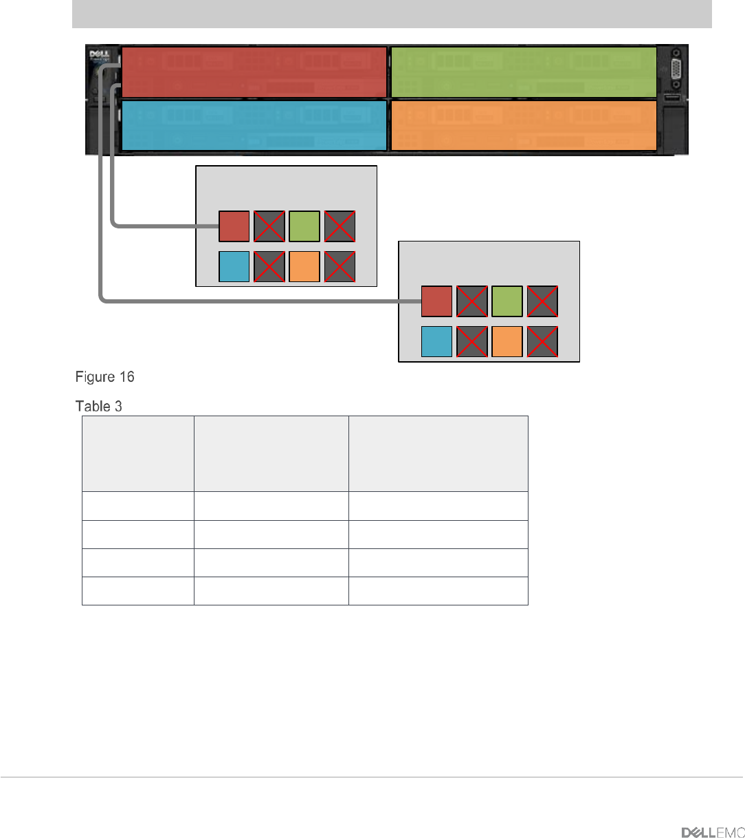
In half-height slots with dual-port CNAs installed in the server blades, the servers map to a single port
on each of the two IOAs. Figure 16 and Table 3 present the port mapping for half-height slots with
dual-port CNAs.
Note: Ports 2, 4, 6 and 8 are not used when using half-height blades with dual-port adapters.
Slot 2
Slot 3 Slot 4
FN2210S IOA A1 (Top)
Internal Ports
5 6
3
7
4
8
21
FN2210S IOA A2 (Bottom)
Internal Ports
5 6
3
7
4
8
1
Slot 1
2
IOA Port mapping half-height slots with dual-port CNAs
Half-height slots with dual-port CNAs
Slot
IOA A1
port
numbers
(top)
IOA A2 port
numbers
(bottom)
1
1
1
2
3
3
3
5
5
4
7
7