
Deployment Guide
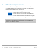
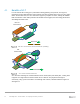

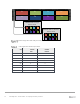
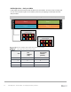
Table Of Contents
- 1 Introduction
- 2 The Dell FX2 and FN I/O Modules
- 3 Initial out-of-box connectivity check and default settings
- 4 VLT and the example environments
- 5 FN IOM Dell Blade I/O manager and internal port mapping features
- 6 Environment One: Basic VLT deployment with VLT mode
- 7 Environment Two: Dell Networking switches with mVLT and IOM in Full Switch mode
- 8 Environment Three: Dell Networking switches with mVLT and FN IOM in programmable MUX mode.
- 9 Environment Four: VLT interoperability with Cisco vPC
- A References
- B Components
- C Terminology
- D Reset FN IOM to Default Factory Configuration
- E FN IOM initial out-of-box configuration and default settings
- F Support and feedback

14 PowerEdge FX2 – FN I/O Module – VLT Deployment Guide | Version 2.2
NIC Port 1
NIC Port 2
TEAM
Internal
Connections
Te0/1
Te0/1
Blade Server 1
FN410S-A1
FN410S-A2
PowerEdge FX2
Chassis
Internal interfaces
participating in VLT
VLT member/
interfaces
VLTi / ICL peer link
Physical Connectivity in a PowerEdge FX2 Chassis Using IOMs
NIC1
NIC2
TEAM Virtual
Interface
PowerEdge FX2
Chassis
Logical view of Teamed Virtual
Interface connected to two IOMs as
one logical switch
Logical Connectivity in a PowerEdge FX2 Chassis Using IOMs