
Deployment Guide
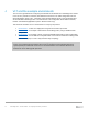

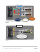

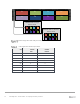
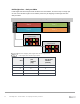
Table Of Contents
- 1 Introduction
- 2 The Dell FX2 and FN I/O Modules
- 3 Initial out-of-box connectivity check and default settings
- 4 VLT and the example environments
- 5 FN IOM Dell Blade I/O manager and internal port mapping features
- 6 Environment One: Basic VLT deployment with VLT mode
- 7 Environment Two: Dell Networking switches with mVLT and IOM in Full Switch mode
- 8 Environment Three: Dell Networking switches with mVLT and FN IOM in programmable MUX mode.
- 9 Environment Four: VLT interoperability with Cisco vPC
- A References
- B Components
- C Terminology
- D Reset FN IOM to Default Factory Configuration
- E FN IOM initial out-of-box configuration and default settings
- F Support and feedback
13 PowerEdge FX2 – FN I/O Module – VLT Deployment Guide | Version 2.2
4.1 Benefits of VLT
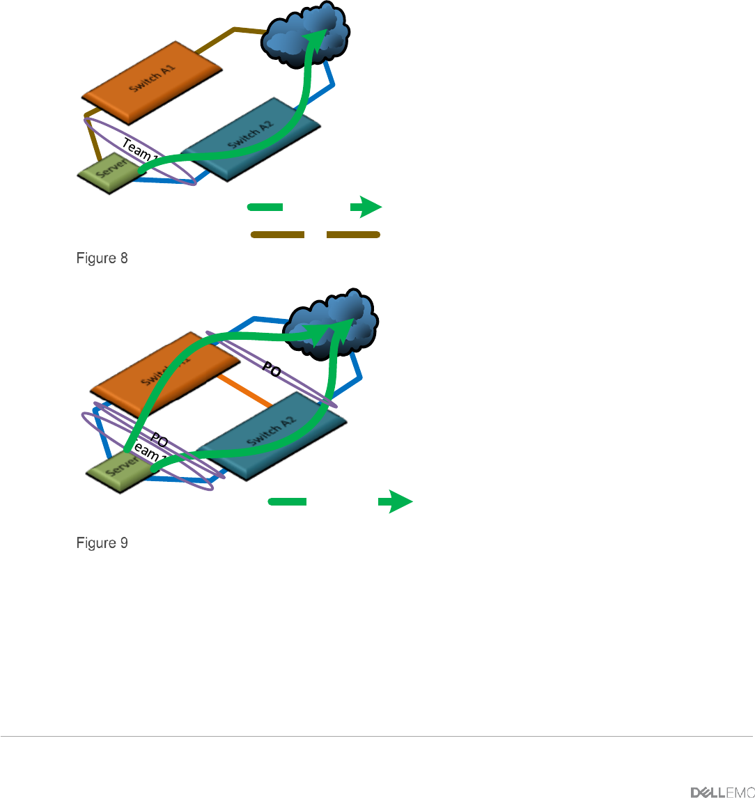
In a non-Virtual Link Trunking (VLT) environment utilizing spanning tree protocol, as in Figure 8,
redundancy involves idle equipment and increased costs with no added value in the event of a device
failure. On the other hand, in a VLT environment (Figure 9), all paths are active, utilizing all available
links and switches to their fullest potential. This doubles the throughput, thus increasing performance
and adding immediate value.
Non-VLT
Environment
Active Path
Idle
Non-VLT Environment with Active/Passive (Standby)
VLT
Environment
Active Path
VLT Active-Active Environment
VLT also takes advantage of teamed Network Interface Cards (NICs) and switch pairs, causing them
to appear as a single switch to devices outside the VLT domain. The physical versus logical
connectivity, using a pair of FN IOMs in a PowerEdge FX2 chassis, is illustrated below in Figure 10
and Figure 11.