
Deployment Guide

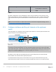
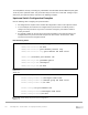

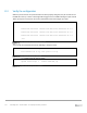

Table Of Contents
- 1 Introduction
- 2 The Dell FX2 and FN I/O Modules
- 3 Initial out-of-box connectivity check and default settings
- 4 VLT and the example environments
- 5 FN IOM Dell Blade I/O manager and internal port mapping features
- 6 Environment One: Basic VLT deployment with VLT mode
- 7 Environment Two: Dell Networking switches with mVLT and IOM in Full Switch mode
- 8 Environment Three: Dell Networking switches with mVLT and FN IOM in programmable MUX mode.
- 9 Environment Four: VLT interoperability with Cisco vPC
- A References
- B Components
- C Terminology
- D Reset FN IOM to Default Factory Configuration
- E FN IOM initial out-of-box configuration and default settings
- F Support and feedback

104 PowerEdge FX2 – FN I/O Module – VLT Deployment Guide | Version 2.2
E.2 Verify the configuration
When the port channel of the upstream switch has been properly configured, the port channel on the
FN IOM will come up. A series of messages will be logged on the FN IOM indicating that port channel
128 is up and ports connected to the servers downstream have been brought up as well:
Changed interface state to up: Po 128
Downstream interface cleared from UFD error-disabled: Te 0/1
Downstream interface cleared from UFD error-disabled: Te 0/2
Downstream interface cleared from UFD error-disabled: Te 0/3
…etc.
Port channel 128 informational message
You may also run commands such as the following to verify the status:
Dell#show interfaces port-channel 128
Port-channel 128 is up, line protocol is up
Port channel 128 show command
Dell#show uplink-state-group
Uplink State Group: 1 Status: Enabled, Up
Uplink State Group show command