Dell EMC Server Deployment Pack Version 4.
Notes, cautions, and warnings NOTE: A NOTE indicates important information that helps you make better use of your product. CAUTION: A CAUTION indicates either potential damage to hardware or loss of data and tells you how to avoid the problem. WARNING: A WARNING indicates a potential for property damage, personal injury, or death. Copyright © 2009 - 2017 Dell Inc. or its subsidiaries. All rights reserved. Dell, EMC, and other trademarks are trademarks of Dell Inc. or its subsidiaries.
Contents 1 Introduction....................................................................................................................................................4 What's new in this release.................................................................................................................................................4 Dell EMC Server Deployment Pack features overview.................................................................................................
1 Introduction This document describes the activities that you can perform with the Dell EMC Server Deployment Pack (DSDP) Version 4.0 for Microsoft System Center Configuration Manager (Configuration Manager). NOTE: This document contains information about requirements and the supported software necessary for working with DSDP. If you are installing this version of DSDP after a long time after its release date, check to see if there is an updated version of this document on the support site.
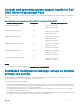
Console and operating system support matrix for Dell EMC Server Deployment Pack The following table provides information about the operating systems supported by Dell EMC Server Deployment Pack for Configuration Manager. Table 1. Compatible operating systems supported by Dell EMC Server Deployment Pack for WinPE Configuration Manager Version WinPE Version Operating system Deployment Configuration Manager 2012 3.0 • • Windows Server 2008 Windows Server 2008 R2 Configuration Manager 2012 SP1 4.
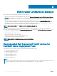
2 Before using Configuration Manager Before you begin using the Configuration manager, ensure the following: • Import the DTK packages if you are upgrading DSDP using the option Remove Dell Deployment ToolKit (DTK) utilities and Windows PE drivers or installing DSDP for the first time. For more information about importing a DTK package for System Center Configuration Manager, 2012 SP2, 2012 R2 SP1, 2012 R2, 2012 SP1, or 2012, see Importing a DTK Package for hardware configuration and OS deployment.
NOTE: In System Center Configuration Manager, there are only Windows PE 10.0 drivers, so only 64–bit operating systems’ deployment is supported as DTK version 5.5 does not support 32–bit version of Windows PE 10.0 drivers. NOTE: In Configuration Manager 2012 SP2, Configuration Manager 2012 R2 SP1, and Configuration Manager 2012 R2, there are only Windows PE 5.0 drivers, so only 64–bit operating systems’ deployment is supported as DTK version 5.5 does not support 32–bit version of Windows PE 5.0 drivers.
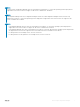
3 Using the Dell EMC Server Deployment Pack on systems running System Center Configuration Manager, 2012 SP2, 2012 R2 SP1, 2012 R2, 2012 SP1, or 2012 This section provides information about how to use Dell EMC Server Deployment Pack on systems running System Center Configuration Manager, 2012 SP2, 2012 R2 SP1, 2012 R2, 2012 SP1, or 2012. Topics: • Dell Driver CAB files • Dell Deployment ToolKit • Importing Dell Server Driver Packages Dell Driver CAB files A cabinet (.
Upgrading Dell Driver CAB files 1 Launch Configuration Manager Console. 2 In the left pane, select Software Library > Overview > Application Management > Packages. 3 Right-click Packages and select Dell PowerEdge Server Deployment > Launch Deployment Toolkit Configuration Wizard. The PowerEdge Deployment ToolKit Configuration Wizard screen is displayed.
Customizing boot image and deploying OS through Dell Driver CAB files After importing Dell Driver CAB files, perform the following tasks: 1 Creating a Boot Image for Deploying PowerEdge Servers. 2 Enabling Command Prompt for Debugging Boot Images. 3 Distributing Content and Updating Distribution Points. 4 Configuring the Task Sequence Steps to Apply Operating System Image And Driver Package. 5 Deploying a Task Sequence. 6 Methods for deploying task sequence.
The drivers imported from DTK or CAB are injected into WinPE. This process depends on the Microsoft System Center Configuration Manager and ADK. It is recommended that you read the limitations documented for these products before creating a boot image. For example, technet.microsoft.com/en-us/library/hh825070.aspx NOTE: You can view the DTK configuration details only by using the PowerEdge Deployment ToolKit Configuration Wizard.
Applying the operating system image NOTE: Before you begin this task, make sure that you have the required operating system image file (.wim file) within the Operating System Images tree in the Configuration Manager. To apply the operating system image: 1 In the left pane of the Task Sequence Editor, under Deploy Operating System, click Apply Operating System Image.
Importing a DTK package for hardware configuration and OS deployment 1 Download DTK .exe from Dell.com/support. NOTE: Ensure that you import a DTK Package from the site server. 2 Launch the Configuration Manager Console. 3 In the left pane, select Software Library > Overview > Application Management > Packages. 4 Right-click Packages and select Dell PowerEdge Server Deployment > Launch Deployment Toolkit Configuration Wizard.
8 Configuring the Task Sequence Steps to Apply Operating System Image And Driver Package 9 Deploying a Task Sequence 10 Methods for deploying a task sequence System Lockdown Mode The System Lockdown Mode feature is available in iDRAC for 14th generation of the PowerEdge servers. This feature when enabled locks the system configuration modification tasks. This feature is intended to protect the system from unintentional changes.
Creating a task sequence You can create a task sequence in two ways to configure your server: • Create a Dell-specific task sequence using PowerEdge Server Deployment template. • Create a custom task sequence. The task sequence proceeds to the next task sequence step irrespective of the success or failure of the command. Creating a Dell specific task sequence To create a Dell-specific task sequence using PowerEdge Server Deployment template: 1 Launch Configuration Manager Console.
Editing a task sequence 1 Launch the Configuration Manager Console. The Configuration Manager Console screen is displayed. 2 In the left pane, select Software Library > Operating Systems > Task Sequence. 3 Right-click the task sequence that you want to edit and click Edit. The Task Sequence Editor window is displayed. 4 Click Add > Dell Deployment > Apply Drivers from Dell Lifecycle Controller. The custom action for your Dell EMC Server Deployment Pack is loaded.
NOTE: Ensure that the MAC address for each target matches the MAC address of the target’s NIC port that is connected and active on the network. NOTE: If EnableDHCP is true, the values of IPAddress, SubnetMask and IPGateway are ignored, but DNS fields are used to set DNS Servers for both WinPE and post OSD network settings. Importing targets 1 In the left side of Configuration Manager, expand Assets and Compliance, right-click Devices, and select Import Computer Information wizard.
3 From the Configuration action type drop-down list, select BIOS Config (ini file). The View button is enabled. NOTE: You can also select BIOS Config (command line) if you want to configure the system by using the CLI option. For more information about the CLI option usage, see Command Line Options. 4 Click View to open the .ini file. Make modifications as per the configurations required and save the file. For information about the .
NOTE: For information about the .ini file format, see the “Sample File Formats” section in the latest Dell OpenManage Deployment Toolkit Command Line Interface Reference Guide available at Dell.com/support/manuals. 1 Click View to see the existing syscfg.ini file. 2 In the Configuration File Editor window, edit the syscfg.ini file, select the Save these changes to the existing file in the toolkit package when I click OK option and click OK. Edit This is a sample raidcfg.ini file.
Configuring iDRAC 7 and iDRAC 8 using XML input To configure idrac 7 and idrac 8 using XML input: 1 Right-click the task sequence and click Edit. 2 In the left side of the Task Sequence Editor, under Configure Hardware > Step 1 , click set iDRAC7 Config (xml file) > Action Settings tab. For iDRAC 8, click Configure Hardware > Step 1 , click set iDRAC8 Config (xml file) > Action Settings 3 From the Configuration action type drop-down list, select iDRAC 7 Config (xml file).
b c d 2 Edit the task sequence and from the Action drop-down list, select Get. a b c d e f g 3 In Server Hardware, select Set BIOS config. Select the appropriate boot image, credentials, and other inputs. Click Create and Save the Task Sequence. Right-click on the task sequence and click Edit. Delete the step Build the Reference Machine as deploying OS is not required. Click Set BIOS Config (ini file). Change the action to Get. In Configuration File/Command line parameters, provide a filename.
1 Select from the Configuration file/Command line parameters drop-down menu. 2 Click Import. 3 Specify the location of the configuration file you want to import and click Open. 1 From the Configuration file / Command line parameters drop-down list, select . 2 Click View. The Array Builder wizard for the sample.xml is displayed. 3 To edit the sample.xml, see .
When a controller is created, a default variable condition, array, and disk(s) are created to ensure a valid configuration. You can leave the controller unconfigured - with disks set to non-RAID, or you can add arrays or do other actions. NOTE: If the disk(s) is set to non-RAID, the existing RAIDs are cleared when the variable condition is not met. Adding a controller 1 Select a controller from the list, or select an embedded controller. The Controllers drop-down menu is enabled.
Adding a new variable condition To add a new variable condition under an embedded controller: 1 Expand Embedded Controller and select [No variable conditions defined]. 2 Click Variables > New Variable Condition. The Variable Condition Configuration window is displayed. 3 Under Variable Matching Criteria, you can set a rule to apply this variable only if it matches certain criteria that you select. 4 Click OK to apply the variable condition or Cancel to return to Array Builder.
Logical drives (also known as virtual disks) Logical drives are present on RAID arrays and non-RAID groups. While configuring the logical drives you can allocate a specific size (in GB) or allocate all the available (or remaining) space in the array to them. By default, a single logical drive is created for all new arrays and is set to use all the available space.
• Multiple disks • Hot spare (only for the current array) • Global hot spare (all arrays) Changing a disk To change a disk, click on the disk and select Disks > Change Disk. You can change a disk to: • Standard disk • Hot spare (only for the current array) • Global hot spare (all arrays) Deleting a disk To delete a disk, click on the disk and select Disks > Delete Disk. Exporting to XML This menu item allows you to save the current configuration in an XML file to a location of your choice.
Table 2. Creating Task Sequences for RAID, DRAC, and iDRAC Option Suboptions Description RAID Configuration (.ini file) 5i-raid0.ini Sample file for RAID 0. 5i-raid1.ini Sample file for RAID 1. 5i-raid5.ini Sample file for RAID 5. raidcfg.ini Use the existing raidcfg.ini file to configure RAID. For a similar example, see . iscsicfg.ini Use the existing iscsicfg.ini file to configure RAID. For a similar example, see .
Option iDRAC Configuration (iDRAC9) Suboptions Description idrac8cfg.ini Use the existing idrac8cfg.ini file to configure iDRAC8. For a similar example, see . For more information about the BIOS option, see . For more information about the BIOS option, see . idrac9cfg.ini Use the existing idrac9cfg.ini file to configure iDRAC9. For a similar example, see
Retrieving log files or capturing configuration files 1 Select Retrieve the task sequence log file from the client after this action runs. 2 Select Enable extended / debug logging by this action to get extensive information in the log files. 3 Select Retain network folder settings from a prior step, if available to copy any available network folder settings from the previous step or to configure the network folder settings proceed to step 4. 4 Enter a valid network/local path to save the file.
4 Troubleshooting NOTE: Before you run the sample commands provided in the troubleshooting section, see the DTK documentation and if required recreate the commands based on machine configuration. An error occurs while trying to apply RAID on a system using command line interface When you try to apply RAID using Command Line Interface on a system where an earlier version of RAID is already configured, an error is displayed.
5 • In Task Sequence Variable, type SiteServer. • In Value, type . For example: ss1.abc.com • Click Apply and then click OK. Distribute and Update the PowerEdge Custom Reboot Script and PowerEdge Deployment Toolkit Integration packages. NOTE: During upgrade, the boot image is removed, you must create a boot image, link the boot image to the task sequence, and then inject the drivers into the boot image.
5 Command line options DSDP supports the command line options supported in Dell Deployment Toolkit. For more information about the command line options, usage guidelines, and syntax, see Dell OpenManage Deployment Toolkit Version 4.4 Command Line Interface Reference Guide.
Mandatory Options and Arguments Optional Parameters Valid Parameters Arguments vdname= controllerid= id Description Example: A:>raidcfg -vd -vd=2 -ac=svdn vdn=xxx -c=2 RAIDCFG Command successful! When using this command in DSDP, remove raidcfg and run the command.
6 Other Dell documents you might need In addition to this guide and the online help, you might need to refer the following documents to get details on specific Dell OpenManage products. These documents are available at Dell.com/support/manuals. • The Dell EMC Server Deployment Pack Version 4.0 for Microsoft System Center Configuration Manager Installation Guide provides information about installing DSDP 4.0 on your system.
• For Dell EMC Enterprise Systems Management documents — Dell.com/SoftwareSecurityManuals • For Dell EMC OpenManage documents — Dell.com/OpenManageManuals • For Dell EMC Remote Enterprise Systems Management documents — Dell.com/esmmanuals • For iDRAC and Dell EMC Lifecycle Controller documents — Dell.com/idracmanuals • For Dell EMC OpenManage Connections Enterprise Systems Management documents — Dell.