SmartFabric Services for OpenManage Network Integration User Guide Release 1.3 August 2020 Rev.
Notes, cautions, and warnings NOTE: A NOTE indicates important information that helps you make better use of your product. CAUTION: A CAUTION indicates either potential damage to hardware or loss of data and tells you how to avoid the problem. WARNING: A WARNING indicates a potential for property damage, personal injury, or death. © 2020 Dell Inc. or its subsidiaries. All rights reserved. Dell, EMC, and other trademarks are trademarks of Dell Inc. or its subsidiaries.
Contents Chapter 1: SmartFabric vCenter.................................................................................................... 5 Chapter 2: SmartFabric Services................................................................................................... 7 SFS for data center leaf and spine fabrics.................................................................................................................... 7 SFS initial setup...........................................................
Import ESXi host profiles from vCenter................................................................................................................ 86 Import SmartFabric discovered server interfaces...............................................................................................90 Configure and manage uplinks....................................................................................................................................... 94 Create L2 Uplink..............................
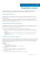
1 SmartFabric vCenter Enterprises are adopting the power of automation to transform their IT operations, and enable a more agile and responsive infrastructure in their data center. Network operators must leverage the power of automation within and across their departmental functions, delivering integrated solutions which cater to cloud-based consumption models.
○ Fabric connectivity extended to PowerSwitches required for VxRail solutions only. ● Improved SLA ○ Fully validated software stack recommendation. ○ Protection from human-error due to predictable and repeatable HCI fabric experience. ● Enhanced support experience ○ World-class Dell EMC HCI and fabric services. ○ Fabric that is integrated into VxRail services and support experience.
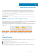
2 SmartFabric Services SFS offers plug and play data center network fabric deployment, expansion, and management of Dell EMC infrastructure as turnkey solutions. SFS is a component of SmartFabric OS10 network operating system that provides the framework to automatically deploy the network as a single logical entity which enables the integration of Dell EMC infrastructure solutions.
Enable SFS This information describes how to enable SmartFabric Services. To enable SFS on a switch from the SmartFabric OS10 command-line interface (CLI), use smartfabric l3fabric enable command and set a role. In SmartFabric mode, the two leaf or ToR switches are automatically configured as a VLT pair, and the VLT interconnect link (ICL) ports must be physically connected before enabling SFS. NOTE: The VLTi ports (ICL ports) cannot be modified once SFS is enabled.
SFS Master SFS uses Keepalive protocol, running on VLAN 4000, to elect one in the fabric as a Master switch. Only a leaf switch can be elected as a Master. In a single SFS domain, there is only one Master switch at any given time, and the rest of the leaf switches are designated as the backup. A new Master is elected from the backup switches when the Master fails to provide high-availability to the fabric. NOTE: Spine switches cannot be elected as a Master node within SFS.
Rack or VLT fabrics When two leaf switches are discovered on specified VLTi ports, a VLT is automatically created between the two switches to form a network fabric called the VLT fabric. This VLT fabric is automatically assigned with a fabric ID, a universally unique identifier (UUID). In a single rack deployment, the network fabric and the VLT fabric represent the same set of switches.
Spanning-tree protocol SFS uses RPVST+ as the default spanning tree protocol to build leaf and spine switches. Spanning-tree protocol is disabled for VXLAN networks. SFS automatically creates user networks as VXLAN networks inside the fabric. For a Layer 2 uplink from the fabric to the external network, the uplink ports in the fabric are configured as VXLAN access interfaces and spanning-tree BPDUs are not sent to the external network. SFS support for MSTP on L3 fabric: By default, the STP mode is RPVST+.
SFS integrated personalities This information describes the two SFS integrated personalities. ● SFS VxRail L2 single rack personality — enables an automated single rack network fabric (L2 fabric profile) for VxRail clusters. Use the L2 personality for the existing fabric deployments. For more information about configuring VxRail L2 single rack personality, see VMware Integration for VxRail Fabric Automation SmartFabric User Guide, Release 1.1, September 2019.
3 OpenManage Network Integration OpenManage Network Integration (OMNI) is a component of SmartFabric Services (SFS) that integrates with VMware vCenter for fabric automation of the physical network infrastructure corresponding to the virtual network operations within vCenter. OMNI also serves as a front-end management application for managing one or more SFS instances, enabling administrators to manage and operate one or more network fabrics that are deployed with SFS.
NOTE: The OMNI portal or SmartFabric Services user interface does not provide localization. When upgrading from older major version to 1.3, follow the instructions for upgrading major version that is provided in Upgrade OMNI appliance. Download and install OVA 1. Download the OVA from OpenManage Network Integration support, and store the OVA image locally. 2. In the vSphere Client, select Hosts and Clusters, right-click the cluster that the plug-in must manage, and select Deploy OVF Template. 3.
5. Select the destination compute resource, and click Next. 6. Review and verify the template details, and click Next. 7. Accept the end-user license agreement (EULA), and click Next.
8. Select the VSAN datastore for the configuration and disk files, and click Next. 9. Select a destination network for each network source, and click Next. The VxRail Management Network must be assigned to the VxRail internal Management network. The default VLAN ID for this network is 3939. The vCenter Server network must be connected to the port group where the vCenter Server is reachable for deployment of the OMNI plug-in.
10. Click Finish to start creation of the VM. Power on OMNI VM 1. Click Recent Tasks and scroll to the bottom of the window to view the status, and wait for the deployment to finish.
2. Select the OMNI VM you want to power on, and select Actions > Power > Power On. 3. Select Launch Web Console.
Set up OMNI This information describes how to log in to the VM console, and also explains the OMNI vCenter setup. Log in to VM console Configure OMNI through the VM console after completing the authentication step. By default, the VM console automatically closes after 10 minutes, but can be customized. 1. Enter admin for both the default username and password. 2. If it is a first-time login, the system prompts for password change.
After the passwords are successfully updated, self-signed certificates are created. You can change the certificates later with OMNI management menu options. NOTE: The sudo password is the same as the password set for the admin user. NOTE: Root user is disabled by default. To set the password to enable root user, use the OMNI VM console CLI menu. You can only access root user through the console.
NOTE: Edit a connection menu displays edit option of Bridge interface docker0. Do not modify any configuration of the docker0 interface as it can lead to OMNI appliance failure or unexpected OMNI behavior. 3. Select Wired connection 1, then click Edit. 4. Verify Ethernet (ens160) is connected to the vCenter reachable network, then change the Profile name to vCenter Server Network. 5. Change the IPv4 configuration from Automatic to Manual from the drop-down.
6. Click Show to the right of IPv4 configuration, then click Add. 7. Set the Manual IPv4 address, Gateway address, DNS servers, Search Domains, then click Edit to the right of Routing. 8. On IPv6 configuration, select Ignore for the IPv6 configuration, then click OK. NOTE: IPv6 configuration is only required for an in-band network.
You are now ready to continue configuration. NOTE: If you are not connecting the OMNI VM to a SmartFabric local-link, ignore this part as it not applicable and you are ready to activate the connection profile. 1. Select Wired connection 2, and click Edit. 2. Rename Profile name to VxRail Mgmt Network.
3. Select Disabled for the IPv4 configuration. 4. Select Link-Local for the IPv6 configuration. 5. Click Edit to the right of Routing, and click Add.
6. Enter the custom route as fde1:53ba:e9a0:cccc::/64, and click OK. 7. One custom route is now configured, click OK.
8. Click Back to activate the connection profiles. Activate connection profiles NOTE: To populate DNS entries automatically, deactivate and active each profile. 1. Select Activate a Connection, and click OK.
NOTE: If you change while editing a connection, you must deactivate then activate the connection for the respective interface profile. 2. Select the vCenter Server Network profile, and click Deactivate. Repeat for VxRail Mgmt Network. 3. Select the vCenter Server Network profile, and click Activate. Repeat for VxRail Mgmt Network. 4. Click Back, select Set system hostname, and click OK.
NOTE: If you are setting the hostname of OMNI, ensure you have the DNS entry of the OMNI hostname. 5. Enter omni for the hostname, and click OK. 6. The hostname is now set. Click OK. 7. Click Back, and OK to exit the network management UI.
8. Enter a valid NTP Server IP address or hostname, and click Enter. 9. Enter n to not install the SSL certificate from remote server. When you enter n, the self-signed certificate that is created locally is installed.
NOTE: To install a new certificate, see Generate and install SSL certificate. NOTE: If the NTP Server is not configured, the OMNI appliance VM synchronizes with the ESXi server time zone. Generate and install SSL certificate OMNI Management menu has options to generate self-signed SSL certificates or install SSL certificates from remote server. Generate self-signed SSL certificate To generate a self-signed SSL certificate: 1. From the OMNI management menu, select 5. Password/SSL configuration menu. 2.
3. Register or update the OMNI appliance with vCenter for applying the new SSL certificate. From the OMNI management menu, select 4.Register/update OMNI vSphere client plug-in with vCenter. NOTE: Refresh the browser to view the OMNI UI plug-in from the vCenter when you register or unregister OMNI 1.3 VM appliance with vCenter 7.0. For older versions of vCenter, log out and log in to access the plug-in from the vCenter.
Install SSL certificate from remote server To install SSL certificate from remote server: 1. Generate SSL certificate using a standard method in .pem or .crt formats. 2. Copy the generated files to the remote SCP server. 3. From the OMNI management menu, select 5. Password/SSL configuration menu.
4. Enter the selection as 4. Install SSL certificate from remote server to install the certificate. Enter the remote SCP server IP address or hostname and login to the SCP server. Provide the path to the certificate and private key in the server. The files are copied to the OMNI VM. 5. Enter y to install the SSL certificate. 6. Register or update the OMNI appliance with vCenter for applying the SSL certificate. From the OMNI management menu, select 4.Register/update OMNI vSphere client plugin with vCenter.
OMNI vCenter client plug-in registration This information describes how to register the vCenter plug-in. SSL certificates have been automatically generated after the password is successfully updated. For more information, see Log into VM console. NOTE: Multiple OMNI instances cannot be mapped to a single vCenter instance. If a situation where multiple VxRail clusters exist with their own respective fabric instances, it is recommended to map these fabric instances to a single vCenter instance.
2. Select 4. Register/Update OMNI vSphere client plugin with vCenter. 3. Enter the OMNI IP or FQDN for registration with the vCenter instance. NOTE: The recommendation is to use FQDN instead of the IP address of OMNI.
4. Enter the vCenter Server FQDN, vCenter Server username, and vCenter Server password. Repeat this step to register each vCenter instance (up to 10). 5. The OMNI application server services start successful; press [enter] to continue.
6. Select 9. Logout. NOTE: You cannot register the same vCenter instance from another OMNI plug-in. For more information about how to unregister OMNI with vCenter, see Manage vCenter with OMNI.
4 OMNI vCenter integration This information describes the OMNI vCenter integration to automate vCenter PortGroup VLANs. vCenter VSS and DVS PortGroups When you configure PortGroups of a virtual standard switch (VSS) with VLANs and distributed virtual switch (DVS) with VLANs on the OMNI registered vCenter, the respective active and standby physical adapter interfaces are automatically configured by OMNI on the SmartFabric ServerInterfaces. This is shown as tasks on the registered vCenter tasks pane.
4. Append networks that are not created by the OMNI user interface (all networks except the one that has Network Originator set to Manual) to SmartFabric uplink of the type Default or CreateOnly. OMNI automates network addition on one of the fabric uplinks. If you edit the network on the uplink using the OMNI UI and add or edit Network of Originator type Auto, the automation process may remove that network. 5.
5 OMNI appliance console CLI menu This information describes the menus available to the admin SSH user through the console. Table 6. OMNI appliance console CLI menu Menu option Submenu option Description 1. Show version — Display OMNI virtual appliance and plugin version. 2. Interface configuration menu 1. Show interfaces Display OMNI network interface configuration. 2. Show connection status Display OMNI network interface connection status. 3.
Table 6. OMNI appliance console CLI menu (continued) Menu option Submenu option Description 7. Exit — 4. Register or update OMNI vSphere client plug-in with vCenter — Register OMNI with vCenter; enter OMNI IP or hostname, vCenter IP or hostname, vCenter administrator user (administrator @vsphere.local), and vCenter password. It is recommended that you register OMNI appliance user interface with one or multiple vCenters. 5. Password or SSL configuration 1.
After you create the OMNI virtual appliance and complete the virtual appliance setup, launch the OMNI appliance management UI. To access the OMNI Appliance Management UI: Open a browser session, go to https:// OMNI_IP /omni with the IP address or hostname of the OMNI VM that is configured during the initial setup. NOTE: Access OMNI Appliance Management UI only with OMNI VM appliance administrator credentials.
Services menu displays the list of OMNI management and automation services running on the OMNI appliance. Select the automation service of the relevant vCenter and SmartFabric combination and start the services manually. Also start, stop, and restart the automation services individually. Click Refresh icon to update the data and display the updated contents. Start fabric automation services To start the fabric automation services: 1. From the OMNI Appliance Management UI, click Services tab menu. 2.
3. The system displays start service success message. Stop fabric automation services To stop the fabric automation services: 1. Select the relevant automation service that you want to stop, and click Stop. 2. The system displays stop service success message.
To restart the fabric automation service, select the relevant automation service, and click Restart. View the status of automation service in the OMNI VM Home page, see View vCenter Host Automation status. Download Support Bundle 1. Support options are used for debugging. If there is an issue, download a support bundle containing all the logs that are found in OMNI. Also change the log-level of OMNI to collect logs of different types.
Related Videos OMNI Appliance Management UI 46 OMNI appliance console CLI menu
6 Access to OMNI Fabric Management Portal This information describes how to access SmartFabric vCenter through the vSphere Client. A shortcut is available from the vSphere Client left-pane within the menu drop-down and shortcuts view. Access OMNI portal using registered vCenter Before you use the plug-in, you must set up an OMNI appliance in vSphere. Once you register OMNI with vCenter, an OMNI plug-in is available in the vCenter. NOTE: vCenter 7.0 supports plug-in autodiscovery feature.
Access OMNI portal using the OMNI IP address Once the vCenter registration steps are complete, you can log in to the OMNI UI using the OMNI stand-alone page. This information describes how to access the OMNI UI from a browser. 1. Open a browser session, go to https:// OMNI_IP /delawareos10 with the IP configured during setup. 2. Enter the username and password for the OMNI VM, then click Sign In.
Once the username and password are authenticated, the OMNI page displays.
OMNI Fabric Management Portal Once you log in to the OMNI UI using the OMNI appliance IP, you can use the OMNI to manage the SmartFabric instances. From the Home page, you can: ● ● ● ● ● ● Add a SmarFabric instance manually. Configure OMNI autodiscovered SmartFabric instance. Enable or disable OMNI Maintenance mode. View the vCenter host automation status. Manage vCenter with OMNI. View Plugin information links. Add SmartFabric instance This information describes how to add SmartFabric instances in OMNI.
4. Enter the service instance name, username, and password. Click Add. 5. The system displays service instance creation success message.
Configure OMNI autodiscovered SmartFabric instance This information describes how to configure OMNI autodiscovered SmartFabric instances. If the OMNI virtual appliance is connected to a link-local network on SmartFabric (such as VxRail Management Network-VLAN 3939), find the SmartFabric IPv6 VIP autodiscovered by OMNI. For complete information about discovery, see mDNS service in Fabric creation. Edit the autodiscovered SmartFabric instance for the REST_USER password to complete the configuration. 1.
NOTE: After you configure the SmartFabric instance, start the fabric automation services from the OMNI appliance management User Interface (UI). 4. The system displays service instance configuration success message. Manage vCenter with OMNI You can unregister vCenter and manage vCenter credentials with OMNI. Unregister vCenter with OMNI 1. From the Home page, go to vCenter Credentials pane. 2. Select the vCenter from the list, and click Unregister.
3. Click Unregister to confirm. Update the credential of the registered vCenter 1. Select the existing vCenter from the list, and click Update to update the credentials. Update Credential window appears. 2. Enter the required information to edit (user and vCenter fields are automatically populated), then click Update.
3. The system displays an update success message. Enable and disable OMNI Maintenance mode The OMNI Fabric Management portal Home page displays the mode of each service instance in the OMNI VM. Enabling Maintenance mode disables zero-touch automation for all SmartFabric instances. Enabling Maintenance mode prevents OMNI from configuring networks on SmartFabrics when there are changes in the vCenter port groups. Enable Maintenance mode To enable Maintenance mode for a service instance: 1.
2. Click Ok to confirm. 3. The system displays Maintenance mode change success message. Disable Maintenance mode To disable Maintenance Mode for a service instance: 1. From the Home page, under Service Instance, click Under Maintenance for a specific Service Instance from the list. Click Ok to confirm. NOTE: Once the status changes to In Service, go to the OMNI Appliance Management UI to start the relevant automation services. 2. Click to confirm. 3.
Plugin information links You can view the links to documentation and end-user license agreement (EULA). 1. Plugin Information Links has links to: ● Documentation ● End User License agreement 2. Click EULA to view the Dell EMC End User License Agreement.
3. Click Documentation to view the User Guide and Release Notes uploaded at www.dell.com/support.
7 OMNI SmartFabric Management This chapter explains how to manage SmartFabric components or entities using OMNI. The OMNI VM displays the list of manually created service instances, and the OMNI autodiscovered SmartFabric instances. For more information about the service instances, see OMNI Fabric Management Portal. After you log in to the OMNI Fabric Management Portal, you can access and manage the SFS entities that are configured in a service instance.
View node details To view the details of the nodes or switches in the fabric, select the Service Instance > Summary > Fabric Nodes. From Fabric Nodes, view the list of spine and leaf nodes that are deployed in the fabric. The page displays node information of the selected spine fabric structure which is arranged in racks. Select the Fabric ID to view the fabric details. Each spine fabric has corresponding switches. Each switch includes status (online or offline), name, model, version, role, and IP address.
View fabric topology The Topology tab displays the graphical topology of the network fabric for the selected service instance. You can also view the details of the switch in the fabric. Select the Service Instance > Topology. NOTE: In this release, this feature is marked as beta. The topology view displays the graphical icons of all the nodes and the link connectivity between the nodes. Each graphical node is represented with their service tag.
Manage switches in a fabric You can manage the list of spine and leaf switches available in a fabric. From Switches page: ● ● ● ● ● ● View the details of the switches and the ports in a fabric. Edit the interface details. Set the MTU value for the port. Manage the unused ports in the switches. Configure breakout ports in leaf switches. Configure jump port. View switch and port details View the details of the leaf and spine switches, and the list of all ports and unused ports available in each switch.
2. Select the arrow of the respective leaf or spine switch to view more information. Spine Switches—Displays the list of all spine switches with ports information in categories. Click the arrow of the respective switch and category to view more about port information. Leaf Switches—Displays the list of all leafs in the fabric with ports, unused ports, breakout ports, and jump port information in categories. Click the arrow of the respective leaf switch category to view more information about the ports.
Edit port configuration on a switch Edit the configuration of port on a leaf or spine switch. 1. Select the Service Instance > Switches. 2. Select the spine or leaf switch by clicking the arrow to view more information.
3. Select a port from All Ports category, and click Edit.
4. Edit the name, description, admin status, auto negotiation, and MTU, and click Edit. Configure auto negotiation status You can enable or disable the auto negotiation on a single port or multiple ports. To enable auto negotiation: 1. From All Ports, select a port or multiple ports and click Enable Auto Neg.
2. The system displays a warning message. Click Yes to confirm. 3. The system displays the stage-wise progress of the interface status. To disable auto negotiation: 1. From All Ports, select a port or multiple ports and click Disable Auto Neg.
2. The system displays the stage-wise progress of the interface status. Set MTU value Set maximum transmitting unit (MTU) for the port. 1. Select a port or multiple ports and click Set MTU. 2. Enter the MTU value and click Set.
3. The system displays a warning message. Click Yes to confirm. 4. The system displays the action success or failure message. Manage unused switch ports You can view and manage the unused ports in the switches. To enable or disable unused ports: 1. Select the Service Instance > Switches. 2. Select any spine or leaf switch by clicking the arrow to view the list of ports.
3. Click Unused Ports category to view the list of unused ports available in the switch. 4. Select a port or multiple ports, and click Enable Admin Status. To disable the ports, select a port or multiple ports, and click Disable Admin Status.
The system displays the change status and update success message on completion. Dell Technologies recommends to: ● Enable the port status to operationally up before adding any devices to the port, if the port is disabled using the OMNI UI. NOTE: Devices that are connected to the disabled port are not discovered. ● Ensure that the ports are UP before adding any switches, when you expand the leaf and spine fabric deployments. ● Ensure that the switch port is in UP, when onboarding a server to a leaf switch.
5. The system displays breakout port configured successful or failure message. View port-group properties Select a port to view properties on the right.
Add jump port You can configure only one port in a leaf switch as a jump port. You can select any available port that is not part of an uplink and ICL, and port connected to a server in SmartFabric deployment. To configure jump port: 1. Select the leaf switch from the list, and select the Breakout Ports & Jump Port category. 2. Select the switch to view the properties, and click Jump Port.
3. Enter the Name of the new jump port, select the Interface Name, select the Untagged Network, then click Add.
4. The system displays jump port addition success message. Delete jump port 1. Select the leaf switch for which you want to delete the configured jump port.
2. Select the Jump port, and click Delete. 3. The system displays jump port deletion success message.
Configure server interface profile Server Interfaces Profile page displays a list of Server Profile IDs and their respective onboard status. Select a profile to view details pertaining to that specific profile. You can view information including interface ID, fabric ID, native VLAN, and network name and VLAN ID (if applicable). From Server Interface, you can: ● ● ● ● ● Create a server interface profile. Edit a network in a server interface profile. Edit the ports in a server interface profile.
4. (Optional) Select Yes for the Static Onboarding Option, add Leaf Node and Interface (where the server interface is connected), select the routing protocol as None, and click Create. 5. (Optional) Select Yes for the Static Onboarding Option, select Leaf Node and Interface (where the server interface is connected), select eBGP. Enter the eBGP routing template by entering the name, peer ASN, description, and peer interface IP address, and click Create.
NOTE: In static onboarding, the eBGP or static route routing protocol option is used for NSX-T deployment. 6. (Optional) Select Yes for the Static Onboarding Option, select Leaf Node and Interface (where the server interface is connected), select Static Route, enter the Network Address and Next-Hop Address, then click Create.
NOTE: You cannot delete any created server profile. 7. The system displays server profile and server interface creation successful messages. Create server interface with new server profile To create a server interface with new server profile: 1. Select the Service Instance > Server Interface. 2. Click Create to create a server interface profile and provide server interface ID, then select New Server Profile. NOTE: You can configure duplicate server interface ID.
4. (Optional) Select Yes for the Static Onboarding Option, add Leaf Node and Interface (where the server interface is connected), select the routing protocol as None, and click Create.
5. (Optional) Select Yes for the Static Onboarding Option, select Leaf Node and Interface (where the server interface is connected), select eBGP. Enter the eBGP routing template by entering the name, peer ASN, description, and peer interface IP address, and click Create. NOTE: In static onboarding, the eBGP or static route routing protocol option is used for NSX-T deployment. 6.
NOTE: You cannot delete any created server profile. 7. The system displays server profile and service interface creation successful messages. NOTE: OMNI does not synchronize a statically onboarded interface when it is first added. For the synchronization to happen, a port-group change event on the vCenter must happen or a restart of the automation service for the specific vCenter and SmartFabric instance must occur.
3. Select the server interface ID from the list, and click Edit Networks. 4. Edit the Untagged Network and the Network configuration for the profile, and click Edit. 5. The system displays the server interface profile update success message.
Edit ports on a server interface profile 1. Select the server interface ID from the list, and click Edit Ports. 2. Edit the Static Onboarding Option and the NIC Bonding configuration for the profile, and click Edit. 3. The system displays the server interface profile update success message. Delete a server interface profile You can delete a service interface profile from the service instance. To delete: 1. Select the server interface profile from the displayed list, and click Delete. 2.
Import ESXi host profiles from vCenter Automate onboarding of server interface profile by importing: ESXi host profiles from the registered vCenter—Use this feature to migrate the existing ESXi hosts that are already connected to the vCenter and ready to be onboarded on to the fabric. The feature imports all the required servers to onboard on to the SFS instead of manually configuring the server interface one at a time.
4. Select the relevant cluster, the ESXi host, or the VM NICs available on the ESXi host. ESXi Host Selection window displays the server profile status of the interfaces on the right. NOTE: You cannot select the VM NICs that are already part of a server interface profile in SmartFabric. 5. Click Next to complete the selection of the VM NICs. 6. The Interface Configuration screen displays the list of selected VM NICs.
7. (Optional) Click Edit icon available for each interface to edit the server profile information. Edit the NIC bonding configuration and Static Onboarding. If the static onboarding is No, select an Untagged Network and one or more Tagged Networks and click Update. NOTE: You cannot select same network for both untagged and tagged networks. (Optional) If the static onboarding is Yes, select Leaf Node and Interface (where the server interface is connected), select the Routing Protocol.
NOTE: You cannot edit the server profile that is already configured in the system. 8. Click Add Networks to associate the networks that are part of the fabric for all the server interface profile. Select the networks for Tagged Networks and Untagged Network from the list, and click Add. NOTE: Add networks overwrite the existing networks of all the server interface profiles. 9. Click Finish after all the configurations are complete. 10.
Import SmartFabric discovered server interfaces Automate onboarding of server interface profile by importing: Profiles that are discovered by the SmartFabric—SFS discovers the following types of servers apart from VxRail: ● PowerStore-X ● PowerStore-T Use this feature to onboard new servers that support the Dell-specific LLDP TLVs. When the servers are connected to the fabric, SFS discovers the servers automatically, and the OMNI onboards the discovered servers as part of this workflow.
● (Optional) Select the Routing Protocol as eBGP, enter the ASN and IP address, and click Update. ● (Optional) Select the Routing Protocol as Static Route, enter the Network Address and Next-Hop Address, and click Update.
4. Select one or multiple discovered interfaces, add the service profile and networks, and click Update. For more information about adding server profile and networks, see Add to Server Profile and Add networks sections. Add to Server Profile To add the discovered interfaces to a new or existing server profile: 1. Select one or more discovered interfaces, and click Add to Server Profile. 2. Select the server profile to which you want to add the discovered server interfaces.
3. The system displays the server interface profile association success message. Add Networks To add the networks to the discovered interfaces: 1. Select one or more interfaces from the list, and click Add Networks. 2. Associate the networks with the discovered interfaces, and click Add. ● Select one or multiple networks for Tagged Networks. ● Select a single network for Untagged Network. NOTE: Add networks overwrite the existing networks of all the server interface profiles. 3.
To remove the interface from the server profile, select one or more interfaces from the list, and click Remove from Server Profile. Configure and manage uplinks Configure an uplink and manage the uplinks that are available in the service instance. Using the Uplinks tab, you can: ● ● ● ● View the list of uplinks created in the service instance. Create an uplink. Edit network and port configuration for an uplink. Delete a created uplink.
2. Enter the uplink port type as L2, a Name, an optional description, then click Next. 3. Enter the port configuration by selecting the rack to create the uplink on, select the interfaces, the LAG Mode (LACP or Static), then click Next.
4. Select the untagged network, the OMNI network, and Select Yes or No to integrate the networks that are created automatically in the fabric through vCenter on this uplink. 5. (Optional) Click Create Network to associate a network with the uplink. Enter the name of the network, optional description, and the VLAN number.
6. Click Finish to complete the L2 uplink creation. 7. The system displays user uplink creation success message. Create L3 Uplink Create an L3 uplink of L3 VLAN or L3 routed interface types. Create L3 VLAN uplink 1. Select the Service Instance > Uplink, and click Create. 2. Select L3 for the uplink port type, select L3 VLAN, enter the name for the uplink, and optional description, then click Next.
3. Select the Switch group (Leaf or Spine), select the rack to create the uplink on, select the interfaces, select LACP for the LAG mode, then click Next.
4. Select UnTagged network, select the OMNI network, enter an optional description, select either eBGP or Static Route for the routing protocol, enter the routing policy information, then click Finish. 5. A route is associated with the nodes that are configured in the port configuration. The system displays uplink creation success message. Create L3 routed interface uplink 1. Select the Service Instance > Uplink, and click Create. 2.
3. Select the Switch group (Leaf or Spine), the rack to create the uplink on, select the interfaces, then click Next.
4. Enter the network profile information and routing policy information for the uplinks, then click Finish. 5. The system displays L3 routed uplink creation success message. Edit networks and ports in an uplink You can edit the network and port configuration for an uplink, and also view the detailed information of the uplink. Select the uplink from the displayed list to view the details of the uplink on the right. Edit networks 1. Select the uplink from the list, and click Edit Networks.
2. Edit the Untagged Network associated with the uplink, and click Update. 3. The system displays the uplink interface edit success message. Edit ports 1. Select the fabric uplink from the list, and click Edit Ports.
2. Edit the networks associated with uplink interfaces, and click Update. 3. The system displays the uplink interface edit success message. Delete an uplink You can delete a user-created uplink. To delete: 1. Select the uplink from the displayed list, and click Delete. 2. Click Delete to confirm.
Configure networks and routing configuration You can set up networks and routing configuration. NOTE: Networks that are created by the OMNI user interface are considered Manual. The OMNI vCenter PortGroup VLAN automation process does not add Manual networks to auto uplinks, and does not remove them from SmartFabric. Add Manual networks to uplinks using the OMNI portal if needed. The OMNI VLAN automation process uses Manual networks for ServerInterfaces.
2. 3. 4. 5. Click Create. Verify Layer 2 is selected as the Virtual Network Type. Enter the text for Virtual Network Name, a value for the VxLAN VNI, and the VLT VLAN ID. (Optional) Enter a description, and click Create.
6. The system displays virtual network creation successful message. Virtual network for L3 profile: 1. Select Network from the Network tab, then click Networks > VxLAN Networks. The page displays the list of the VXLAN networks that are configured in the service instance. 2. Click Create. 3. Select Layer 3 as the Virtual Network Type. 4. Enter the text for Virtual Network Name, a value for the VxLAN VNI, the VLT VLAN ID, prefix, gateway IP address, and helper IP address. Click Create.
5. The system displays virtual network creation successful message. View VxLAN network details The VxLAN networks display a list of mapped VLANs. Select a VxLAN network to view details pertaining to that specific network including network ID, VLAN ID, and network name.
Edit VxLAN network You can edit the configuration of VXLAN network: 1. Select a virtual network from the list, then click Edit.
2. Modify the Virtual Network Type. 3. Enter the Prefix, Gateway IP Address, IP address, then click Edit. 4. The system displays virtual network edits success message. Delete VXLAN network To delete a VXLAN network, first delete the mapped VLAN or VLANs if associated, and delete the virtual network. 1. Select the Virtual Network Name, select the Network to remove, then click Delete. 2. Click Delete to confirm. 3. The system displays network deletion success message.
2. Select the Network Type as Layer 2 VLAN Network is selected as the Network Type, enter the Network ID, Network Name, enter 1 to 4093 for the VLAN, enter an optional description, then click Create. 3. The system displays VLAN network creation success message. VLAN networks for L3 profile: 1. Select Networks > VLAN Networks, and click Create.
2. Select the Network Type as Layer 3 VLAN Network is selected as the Network Type, enter the Network ID, Network Name, enter 1 to 4093 for the VLAN, enter an optional description, then click Create. 3. The system displays VLAN network creation success message. Edit network 1. Select a network ID from the list, and click Edit.
2. Modify the details, edit the configuration as necessary, and click Edit.
3. The system displays edit network success message. Delete network 1. Select the VLAN network to remove, then click Delete. 2. Click Delete to confirm.
3. The system displays network deletion success message. L3 routed interfaces This information explains how to create and delete Layer 3 routed interfaces. Create L3 routed interface To create an L3 routed interface: 1. Select Networks > Layer 3 Routed Interfaces, and click Create. 2. Enter the Network ID, Network Name, select the Prefix Length, select the IP Address, enter an optional description, then click Create.
3. The system displays network creation success message. Edit network 1. Select the Network ID from the list, and click Edit. 2. Edit the configuration, and click Edit. 3. The system displays edit network success message.
1. Select the network ID to remove, and click Delete. 2. The system displays network deletion success message. Configure Routes You can configure static routes and eBGP peer routes for a network. Configure static routes Create static route 1. Select Network > Routing Configuration. 2. Select Static Routes, and click Create to add a new static route. 3. Enter the relevant details and click Create.
4. The system displays static route creation is successful. Delete static route 1. Select the static route to delete, and click Delete. 2. Click Delete to confirm.
3. The system displays static route deletion is successful. Add route to switch 1. Select Routing Configuration > Static Routes. 2. Select a static route, and click Add Route to Switch. 3. Select the switch to map to this route, and click Add.
4. The system displays the route added success message. Static route details The static route details display a list of mapped routes. Select a static route to view details pertaining to that specific route including the switch ID. Delete route from switch 1. Select the route to delete, and click Delete Route. 2. Click Delete to confirm the removal of the route from the switch.
3. The system displays route policy deletion success message. Configure eBGP peer route Create eBGP route 1. Select Network > Routing Configuration, and click eBGP Peer Configuration. 2. Click Create to add an eBGP peer route.
3. Enter the relevant details and click Create. 4. The system displays eBGP peer route creation is successful. Delete eBGP route 1. Select the eBGP route to delete, then click Delete. 2. Click Delete to confirm. 3. The system displays route policy deletion success message. View eBGP peer details The eBGP peer details display a list of mapped routes. Select an eBGP route to view details pertaining to that specific route including the switch ID.
Add eBGP route to switch 1. Select an eBGP route, then click Add Route to Switch. 2. Select the switch, then click Add.
3. The system displays the route to switch addition success message. Delete eBGP route from switch 1. Select an eBGP route, then click Delete Route. 2. Click Delete to remove the route from the switch. 3. The system displays route deletion success message. Configure fabric management actions From Fabric Actions pane, you can: ● ● ● ● Change SmartFabric password. Upgrade SmartFabric OS10 image, see Upgrade SmartFabric OS. Replace a switch in a network fabric, see Replace switch in a fabric.
Change SmartFabric password To change the SmartFabric password: 1. Select the Service Instance > Fabric Actions > SmartFabric Password Change.
2. Enter the current password for the REST_USER, the new password, confirm the new password, and click Update Password. 3. The system displays password update success message. Host network inventory You can view information about physical Dell EMC PowerSwitch infrastructure running SmartFabric OS10. Host network inventory page Select a host in vCenter, select the Monitor tab, then select OpenManage Network Integration (OMNI) in the monitor sidebar.
Refresh button Click Refresh to update the host network inventory data and display updated contents. Physical adapter table Select a switch from the Host Network Inventory to view detailed information. The table is default-sorted by descending switch name to group physical adapters belonging to the same switch. ● ● ● ● ● Physical adapter — Name of the physical network adapter. Virtual switch — Name of switch the physical adapter is connected to. MAC address — MAC address of the physical adapter.
● Port groups tab — includes the name of port groups, and VLAN IDs for each port group ● VMs tab — includes the name of VMs of that host that is connected to a single virtual switch OMNI SmartFabric Management 127
View physical switch details Displays information about the onboard interface. This information displays only when there is a physical connection between the VxRail domains and OMNI. When you select a switch from the Host Network Inventory, the page also displays the physical switch information connected to the selected physical adapter.
● ● ● ● Auto Neg — negotiation status of the physical interface Current Speed — current operational speed of the physical interface MTU — maximum transmitting unit configured on the physical interface Native VLAN — untagged default VLAN for the physical switch Networks tab ● Network Name — name of the VLAN network ● Network ID — unique identifier of the fabric network ● VLAN — tagged VLAN of the switch port OMNI SmartFabric Management 129
8 Lifecycle management This chapter explains common lifecycle operations of upgrading the SmartFabric OS10, OMNI appliance, switch replacement, fabric backup, and restore. Upgrade OMNI appliance This section explains how to upgrade the OMNI appliance for major and minor releases. Upgrade OMNI during major releases To upgrade OMNI appliance from older version to 1.3: 1. Prerequisite Save the following details: 2. 3. 4. 5.
2. From the OMNI VM console, select the option 6. Upgrade Appliance. The display lists all the applications which can be upgraded along with the old and new versions. Upgrading requires restarting the services. 3. Enter the SCP server IP address or hostname, username, and the path to the upgrade .zip file and password.
4. Verify all information, then enter Y to continue.
5. Verify the OMNI version.
6. Select 4. Register/Update OMNI vSphere client plugin with vCenter to register the plug-in. 7. Enter the FQDN or IP address to use for registration, then repeat the steps to update the plug-in with the vCenter Server.
Upgrade SmartFabric OS in switch You can upgrade SmartFabric OS from OMNI VM. You can upload an OS10 image to upgrade the fabric. For more information about changing the SmartFabric password, see Configure fabric management actions. You can upgrade OS using the following steps: ● Upload the latest image in the OMNI VM. ● Upgrade fabric using the uploaded image. ● (Optional) Delete the image from the OMNI VM.
Upgrade fabric Upgrade the switches in a fabric with an OS10 image: 1. Select the .bin image, and click Upgrade Fabric. NOTE: Upgrade Fabric option upgrades all the switches in a network fabric. You cannot stop the upgrade after it is triggered. 2. Click Upgrade to confirm. 3. The system displays fabric upgrade success message. SmartFabric automatically reboots when the upgrade is complete. Delete image Delete the OS10 image uploaded in the OMNI VM: 1. Select the .bin image to delete.
2. Click Delete Image. 3. Click Delete to confirm. 4. The system displays delete image is success. Replace switch in a fabric You can replace the faulty OS10 switch in a fabric. To replace: 1. Identify the OS10 switch to be replaced and label each of the cables with the port numbers before disconnecting the cables. 2.
NOTE: Do not remove connections to VxRail nodes until the new switch is in SmartFabric Services mode. NOTE: Ensure that the ICL ports are connected to the other leaf switch which is already in SmartFabric Service mode. 6. Enable SmartFabric Services on the new switch and define the ICL ports. ● For L2 personality—Enable SmartFabric Services on the new switch, and define the breakouts, uplinks, interlink ports, plus any other parameters such as management VLAN, LACP, VLAN tagging, and so on.
● ● ● ● ● ● Set a local or remote repository. Back up the configuration of a select fabric in the OMNI VM. Download the backup files to the local system. Delete the downloaded backup from the OMNI VM. Upload or import the fabric backup file from the local or remote repository to the OMNI VM. Restore the fabric from a backup file. NOTE: The fabric backup and restore features are supported from the OS10.5.0.7 version. If the OS10 software version is less than 10.5.0.
4. The system displays local repository configuration success message. Set a remote repository 1. From Backup and Restore tab, click Set Repository. 2. Select Remote. 3. Select the protocol (SCP or FTP) from the list. Enter the Hostname, Username, and Password details. (Optional) Enter the Repository Path details, and click Submit.
4. The system displays remote repository configuration success message. View repository View the repository details by clicking the information icon. Edit repository You can edit the repository type that is already set. To do so: 1. From Backup and Restore tab, click Edit Repository. 2. Edit the repository type, enter the required details if prompted, and click Edit. NOTE: When you edit the repository from local to remote, the backup files from the local OMNI VM are transferred to the remote repository.
2. Enter the description for the backup file and click Ok. The backup file is stored as a JSON file with the date and time with the GMT timestamp. NOTE: The backup action stores SFS-applied configuration for the whole fabric. Any OS10 system configuration that is done on the individual switches directly has to be backed up using the OS10 CLI. For more information about how to backup the configuration, see Dell EMC SmartFabric OS10 User Guide. 3. The system displays backup completed success message.
The file is downloaded locally with the backup download success message. Delete backup You can delete a backup file from the OMNI VM. 1. Select Backup and Restore tab. 2. Select the backup file that you want to delete from the displayed list, and click Delete. 3. Click Delete to confirm.
4. The system displays backup deleted success message. Upload backup You can upload a backup file from the local system to the OMNI VM. 1. From Backup and Restore tab, click Upload Backup. 2. Enter the description and choose the file that you want to upload, and click Upload. 3. The system displays upload file success message. NOTE: OMNI displays error if the uploaded file is not in the JSON format.
1. Select Fabric Actions > Backup and Restore. 2. Select the backup file from which you want to restore the configuration, and click Restore. NOTE: The restore action reboots all the switches with the applied fabric settings. Any manual configuration that are performed directly on individual switches has to be restored manually using the OS10 CLI. For more information about how to restore the configuration, see Dell EMC SmartFabric OS10 User Guide. 3.
4. To proceed with the restore action, select the checkbox to confirm, and click Restore. Once you initiate the restore process, OMNI appliance changes the service instance state to Maintenance mode automatically, which stops all the fabric automation services specific to the service instance. 5. The system displays the restore success message. When the fabric restore is complete, change the Maintenance mode of the service instance to In Service.
9 Troubleshooting Use the following information to troubleshoot the SmartFabric vCenter OMNI appliance connectivity, SmartFabric errors, and UI population errors. OMNI appliance connectivity Verify the IP address, DNS settings, and connection status. 1. From the OMNI management menu, select 2. Interface Configuration Menu. 2. Enter the selection as 1. Show Interfaces and press Enter.
3. Select 2. Show Connection Status.
Unable to register service instance in OMNI Unable to register the service instances in OMNI, when: 1. SmartFabric is not reachable. To check the SFS connectivity: a. Log in as root user through the OMNI appliance console. b. Check the connectivity of the service instance using the ping command. Use IPv4, hostname, or IPv6 address of the service instance. :~$ ping 100.104.22.22 :~$ping6 c. If ping fails, check if the OMNI interfaces are configured properly.
3. If the NTP server is not configured, select 5. Configure NTP Server, and enter the valid NTP Server IP address or hostname. UI is not populated NOTE: Any IP address or SSL certificate changes on the VM, OMNI automation services can be restarted by changing the status of the service instance to Maintenance mode and then In Service mode. For more information about Maintenance mode, see OMNI Maintenance mode. Check the service status on the plug-in VM. 1.
NOTE: View OMNI management service status is recommended for status validation and debugging purpose. Hence, the output does not show the port numbers. 4. If the problem still persists, try to unregister and register OMNI appliance with vCenter again. Create support bundle Download the support bundle from the OMNI Appliance Management UI. If you cannot access the UI, use to OMNI console to download the support bundle. 1. From the OMNI management menu, enter the selection as 3. OMNI Management Service Menu.
NOTE: The recommendation is to set the log level to DEBUG before creating the support bundle. 3. From an external host, scp using admin credentials to transfer the support bundle file out. SCP credentials for the OMNI appliance are the same as the OMNI appliance console password. By default, admin is used for the username and password. Change log level NOTE: Use OMNI Appliance Management UI to change the log level of each service.
2. Use the arrow keys to go to the line starting with linux and ending with ro quiet. 3. Append init=bin/bash after ro quiet.
4. Press Ctrl-X to boot into the shell with root access. 5. Remount the directory. # mount / -rw -o remount 6. Change the password for admin using passwd admin. Enter the new password and confirm the password.
7. Reset the VM from vCenter and log in through the new password for the OMNI VM. Missing networks on server interfaces If OMNI fails to create and associate the appropriate network on a server interface during automation, OMNI automation services can be restarted so that OMNI reconfigures the networks. OMNI automation services can be restarted by changing the status of the service instance to Maintenance mode, then changing the instance to In Service mode.