
Users Guide
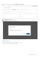
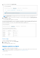
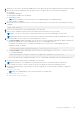
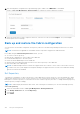

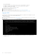
Table Of Contents
- OpenManage Network Integration for SmartFabric Services User Guide Release 2.1
- Contents
- About this guide
- Change history
- Overview of OMNI, SFS, VxRail, and PowerEdge MX
- OpenManage Network Integration
- OMNI vCenter integration
- Access the OMNI stand-alone portal
- Access the OMNI Fabric Management Portal
- OMNI Appliance Management user interface
- SmartFabric management with OMNI
- OMNI feature support matrix
- View SmartFabric instance overview
- View fabric topology
- Manage switches in a fabric
- SmartFabric bulk configuration
- Configure server interface profile
- Configure and manage uplinks
- Configure networks and routing configuration
- Configure global settings for SmartFabric
- View fabric events and compliance status
- OMNI automation support for PowerEdge MX SmartFabric
- OMNI automation support for NSX-T
- Lifecycle management
- Troubleshooting
- Troubleshooting tools
- Unable to add SmartFabric instance in OMNI
- Missing networks on server interfaces
- Unable to launch OMNI UI
- OMNI plug-in does not show service instance
- Unable to register the vCenter in OMNI
- OMNI is unable to communicate with other devices
- Timestamp not synchronized in OMNI
- Reset OMNI VM password

1. Identify the OS10 switch to be replaced and label each of the cables with the port numbers before disconnecting the cables.
2. Back up the following configurations from the faulty switch to configure the new switch with the same details:
● Hostname
● Management IP address
● DNS and NTP IP addresses if configured
● Spanning-tree mode
NOTE: In SmartFabric Services mode, RPVST+ is enabled by default on the uplink interfaces.
● Other nonfabric commands
3. Ensure that the new switch has the same OS version as the faulty switch. You can check the version using the following
command:
OS10# show version
4. Power off the existing switch to prevent data traffic loss in the cluster.
5. Remove the ICL and uplink connections from the existing switch, and connect to the new switch.
NOTE: Do not remove connections to VxRail nodes until the new switch is in SmartFabric Services mode.
NOTE: Ensure that the ICL ports are connected to the other leaf switch which is already in SmartFabric Service mode.
6. Enable SmartFabric Services on the new switch and define the ICL ports.
● For L2 personality—Enable SmartFabric Services on the new switch, and define the breakouts, uplinks, interlink ports,
plus any other parameters such as management VLAN, LACP, VLAN tagging, and so on.
For example, if the uplink port is 1/1/4 and the interlink ports are 1/1/29,1/1/30, no VLAN tagging, LACP auto,
management VLAN 1 as default.
:~$ sfs_enable_vxrail_personality.py -i 1/1/6,1/1/8 -u 1/1/4 -l
● For L3 personality—Enable SmartFabric Services on the new switch using the smartfabric l3fabric enable
role command. Example:
OS10# smartfabric l3fabric enable role LEAF vlti ethernet 1/1/29-1/1/30
For more information about enabling SmartFabric Services, see Dell EMC SmartFabric OS10 User Guide Release 10.5.0.
7. The new switch reboots and is placed in SmartFabric Services mode.
NOTE: During reboot, the configurations are synchronized in the new switch and it takes several minutes.
8. Connect VxRail server ports to the new switch one-by-one to bring up the switch ports and advertise LLDP.
9. Review the command outputs on both switches for same configurations. Use the following commands to validate the
configurations:
● OS10# show vlan
NOTE: The command displays if the switch is a primary or secondary peer.
● OS10# show vlt 255
● OS10# show lldp neighbor
Lifecycle management
143