Management Networks for Dell EMC Networking A guide for providing management access to networked devices using console servers, Ethernet out-of-band, and Ethernet in-band Abstract Large production networks can span across multiple rooms, buildings, or cities, and contain dozens or hundreds of network switches. Using a management network separate from the production network is often desired to configure and manage these environments.
Revisions Date Description May 2019 Initial release The information in this publication is provided “as is.” Dell Inc. makes no representations or warranties of any kind with respect to the information in this publication, and specifically disclaims implied warranties of merchantability or fitness for a particular purpose. Use, copying, and distribution of any software described in this publication requires an applicable software license. © 2019 Dell Inc. or its subsidiaries. All Rights Reserved.
Table of contents Revisions.............................................................................................................................................................................2 Introduction ...................................................................................................................................................................5 1.1 Purpose of this document ......................................................................................................
7.2 Graphical User Interface ...................................................................................................................................28 7.3 Simple Network Management Protocol ............................................................................................................29 Security considerations ..............................................................................................................................................
Introduction Production networks consist of one or more Ethernet switches that carry production traffic data from end to end. Administrators must be able to access the production switches to manage them. For small networks with switches that are physically accessible in the same room, it is easier for the administrator to access and connect to each switch using the console port. This method is used when the initial configuration is performed and may be used for continued management of the switch.
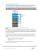
1.3 Production network example Figure 1 is an example of a network topology that contains Dell EMC servers, switches, and other devices. This configuration demonstrates a single rack deployment without any management network. The cloud depicts an existing infrastructure, including spine or core switches, typically found in a data center. Note: Configuration of leaf-spine and other upstream network switches is beyond the scope of this guide.
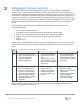
Management network selection There are three management network methods that are commonly used for deploying and managing switches, servers, and other devices on the network: console, out-of-band Ethernet, and in-band Ethernet. The method that is used is based largely on the existing architecture, preference, budget, or a combination of these factors. If a management network is already in place and working satisfactorily, there is little else to do.
2.1 Switch management ports There are various port types available for connecting switches to a management network. The port that is used depends on the category of management network being used and the port that is available on the managed switch. Table 3 provides examples of ports to look for on the switch. Note: For additional information regarding the network ports available with your hardware, see the documentation that comes with your hardware.
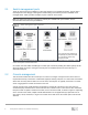
Console Server NMS LAN } Attached devices Console server management topology The application layer protocols are only used on the Ethernet network to connect to the console server. The console server then provides the console port access of the devices being managed. Chapter 3 discusses how to setup console management for configuring and managing devices. 2.3 OOB Ethernet management This connection method uses the dedicated Ethernet OOB port on a device to configure and manage it.
In-band Ethernet management topology Chapter 5 discusses the setup of Ethernet in-band management for the configuration and management of devices on the production network.
Console management Before discussing console servers, it is important to understand how a single console port is used. Console ports on a switch allow users to access the command line interface (CLI) and to configure the switch. Using a cable and physical access to the switch, users can configure the system right out of the box. A computer with an installed terminal emulator is required.
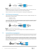
most PCs today is USB. See Table 3 to identify the type of console port you are using on the switch. The console port of the switch being configured will be identified with the symbol “IOIOI”. Once you have identified the two connectors being linked, it is easy to determine which console cable to used. PCs without an RS-232 serial port require a “USB to serial” adapter to connect to a switch with only an RS-232 console port.
Note: Appendix A provides an example of configuring and using a terminal emulator. 3.1.1 USB Type B connectors Some switches have multiple serial ports, and often include a standard RS-232 port and a USB Type B console port. When using a USB Type B console port on a switch, a driver must be installed in the OS of the PC used for the connection. Table 6 shows the required USB Type B drivers for Dell EMC PowerSwitch series switches.
Upstream Management Network Ethernet uplink Console Server Serial Port Connections Serial Port Leaf Switch - Switch serial ports Server serial ports Chassis serial ports Other devices serial ports Serial Port Leaf Switch Serial Port Server Serial Port Server Serial Port Chassis (MX, FX2, etc.
9. Ping the console server from the system where the terminal emulator is installed to confirm that a successful connection is made. The information that is used in section 3.1 for connecting to a single console port, applies when connecting the console ports to the console server. Consult the documentation that is provided with the console server hardware for additional instructions or troubleshooting. Note: Appendix A provides an example of configuring and using a terminal emulator.
Out-of-band (OOB) management networks The OOB management network is a separate network that is solely for management traffic. The network uses the dedicated management port on each switch to connect to a management switch dedicated for management traffic. Production traffic initiated by the network end-users does not traverse the OOB management network.
4.1 Network management switch Dedicated network management switches today are usually 1GbE Base-T switches. These switches are less expensive than most other networked equipment they are being used to manage. Many 1GbE Base-T Ethernet switches on the market provide the features needed to make it a viable management switch. You should select a switch that will provide enough 1GbE ports to connect to all devices you want to manage in the rack.
4.2.2 OS10EE configuration The following commands show how to configure the OOB port on a Dell EMC PowerSwitch series production switch with Dell EMC Networking OS10EE installed. Replace the IP address and management route (default gateway) address with the ones for your network. OS10#configure OS10(conf)#interface mgmt 1/1/1 OS10(conf-if-ma-1/1/1)#no ip address dhcp OS10(conf-if-ma-1/1/1)#ip address 192.168.1.
In-band management networks With in-band management, devices are managed through the production network switches, avoiding the need of purchasing a dedicated management switch. This solution requires that you initially configure each managed switch locally through a serial port connection. An in-band management network is typically used when resources are limited. The cost savings can be realized when used in branch offices or smaller deployments.
count usually provides enough 10GbE ports to connect to all devices in the rack. For this example, rack servers, server chassis, and rack power distribution units (PDUs) were connected. 5.2 Configuring management on production switches To configure the switch to use the in-band connections (front panel Ethernet ports), an IP address is assigned to a VLAN. By default, all IPs can access the management console of the Dell EMC switch.
Configure the VLAN for connections to the upstream and server connections port 1/48 is used for upstream and ports 1/1-1/4 are used for server connections in this example. Provide an interface description and apply an IP address. Tag the ports that will be part of the management VLAN Note: Replace the IP address and VLAN ID shown to match your network. OS9(conf)# interface vlan 10 OS9(conf-if-vl-10)# description Management VLAN OS9(conf-if-vl-10)# ip address 192.168.1.
password credentials for logging in. From the management station or NMS, use the SSH or Telnet application to connect to the managed device. Note: Dell EMC recommends changing the admin password to a complex password during the first login.. 5.3 Control access to management functions In an in-band network, it is important to control the access to the management system (CLI). You can control or limit the Telnet or SSH connections to switch management by applying access lists on VTY lines.
Managing Dell EMC Servers Connecting servers can be achieved using the same methods as a network switch. Connection options include serial port with console redirection, dedicated iDRAC port connected to OOB Ethernet or in-band Ethernet, and shared LOM iDRAC port connected to the in-band Ethernet network.
BIOS settings menu from the serial console Serial Communication options The serial communication screen that is shown in Figure 10, is accessed from the BIOS settings. This screen provides console redirection options and allows the administrator to set the port to COM1 or COM2 and select a baud rate. Refer to the Installation and Service Manual for the Dell EMC PowerEdge server you are attaching to for more information on using the serial port.
6.2 Integrated Dell Remote Access Controller (iDRAC) The integrated Dell Remote Access Controller (iDRAC) is designed to make system administrators more productive and improve the overall availability of Dell EMC PowerEdge server systems. iDRAC alerts administrators about system issues and enables them to perform remote system management. This reduces the need for physical access to the system. 6.2.
iDRAC IP settings in System Setup 6.3 Connecting to Dell EMC Servers (iDRAC) There are two connection options to the iDRAC: the dedicated iDRAC port or shared LOM. Some ToR switches may not be of the same media type or speed in this case a media converter could be used to connect to the dedicated iDRAC Ethernet port. For example, an SFP-1000BASET adapter (Dell EMC part number XTY28) or an SFP+-10GBASET adapter (Dell EMC part number PGYJT) could be used on an SFP switch to connect to the BASE T iDRAC port.
Figure 13 shows a screenshot of the iDRAC settings to use the shared LOM port for iDRAC management. Shared LOM network settings The iDRAC and OS are configured to use the same Ethernet connection. The advantages of using this method are less cabling and the ability to use a second LOM port as a failover port. 6.4 Licensed features in iDRAC7, iDRAC8, and iDRAC9 The types of connections available depend on the licensed features of the iDRAC.
Remote access Once the communication link is established between a management station and a managed device, there are multiple applications that can be used to open a management session with the device. Each application is based on a CLI, GUI, or SNMP interface. This section provides an explanation and sample screens of the three interfaces. 7.1 Command Line Interface The Command Line Interface, or CLI, is an application that is operated through an ASCII terminal.
Access to the GUI is obtained by entering the IP address of the managed device into the URL field of the browser. The syntax is http(s)://switch_mgmt_ip. Figure 14 shows an example of a GUI management screen. This GUI shows a picture of the switch. Green indicates that ports 1 and 2 are up. The GUI is a quick way to find and implement features available on a switch, without the need or understanding of CLI commands.
Security considerations Like a production network, when implementing a management network, Dell EMC recommends that the network administrator take the necessary security measures to ensure the protection and integrity of the data and devices being used. Securing the network infrastructure is a multilayer discipline. The following are security items to consider. • • • • • • Physical security involves physical access to the infrastructure.
A Using a terminal emulator Terminal emulators are commonly used applications for accessing and managing devices on a network. They are used in conjunction with console ports, console servers, OOB Ethernet, and in-band Ethernet management networks. This section provides examples of connecting to a managed device using a Windowsbased terminal emulator. This appendix provides two basic examples: • • A.
Identifying the serial communications (COM) port 4. If more than one console port is listed, a description is provided to help identify it. For example, if you are using a USB adapter, the description says Adapter for USB to COM Port or something similar. 5. If you are unable to positively identify the console port that you have the cable connected to, you can either look in the computer BIOS, or try each (COM1, COM2, etc.), one at a time, in the terminal emulator application using the steps below. A.1.
The look and behavior of the initial prompt that is received depends on the device you are connecting. There are three common behaviors that are associated with an initial connection. One of the following behaviors occurs: • • • Password prompt is displayed - You must enter the password to continue. The default ID and password on Dell EMC PowerSwitch series is admin/admin. Immediate access - No password is required. A setup wizard appears – Use this interview-type program to help with the initial setup.
B Connecting to upstream management Uplink ports on the management switch are used for connecting to the upstream management network. This network can consist of one or more NMS, management stations, and traffic between them and the managed devices. Uplink ports are identified as any Ethernet port that is not the lowest bandwidth on the switch (not including any OOB port).
C LCD Panel If your Dell EMC PowerEdge system is equipped with an LCD panel, it can be used to configure or view the iDRAC IP address of the system. The LCD panel is available only on an optional front bezel. LCD panel showing the iDRAC IP address LCD panel features Item Button or display Description 1 Left Moves the cursor back in one-step increments. 2 Select Selects the menu item highlighted by the cursor. 3 Right Moves the cursor forward in one-step increments.
D Glossary The following terms were discussed in this guide. Access Control List (ACL) – a layer of security used to allow or deny users access to the network. Command Line Interface (CLI) – a user interface that uses typed commands to configure a device. Console port - a hardware port that allows direct communication between two devices using a serial cable. Console Server – a hardware device that allows one-to-many access to console ports of many devices.
E Components used in the examples The following table includes the hardware and software that is used to configure the examples in this guide. Components used in this guide 37 Item Version Dell EMC PowerSwitch S4148F-ON OS10EE v10.4.3.1 Dell EMC PowerSwitch S4048T-ON OS10EE v10.4.3.1, OS9 v9.14.1.3 Dell EMC PowerSwitch S4048-ON OS9 v9.14.1.3 Dell EMC PowerSwitch S3048-ON OS9 v9.14.1.
F Technical resources Dell EMC Networking Guides Dell EMC PowerSwitch S4148F-ON manuals and documentation Dell EMC PowerSwitch S4048-ON manuals and documentation Dell EMC PowerSwitch S3048-ON manuals and documentation Other Dell EMC PowerSwitch Series manuals and documentation Dell EMC OS10EE User Guide Dell EMC OS9 User Guide Dell EMC OS6 User Guide Dell EMC iDRAC User's Guide Dell Deployment Toolkit User Guide OMNM Guides and Documentation 38 Management Networks for Dell EMC Networking
G Fabric Design Center The Dell EMC Fabric Design Center (FDC) is a cloud-based application that automates the planning, design, and deployment of network fabrics that power Dell EMC compute, storage, and hyper-converged infrastructure solutions. The FDC is ideal for turnkey solutions and automation that is based on validated deployment guides. FDC allows design customization and flexibility to go beyond validated deployment guides. For additional information, go to the Dell EMC Fabric Design Center.
H Support and feedback Contacting Technical Support Support Contact Information Web: http://www.dell.com/support Telephone: USA: 1-800-945-3355 Feedback for this document Dell EMC encourages readers to provide feedback on the quality and usefulness of this publication by sending an email to Dell_Networking_Solutions@Dell.com.