
Users Guide
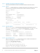
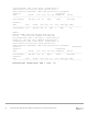

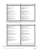
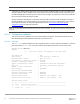
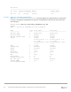
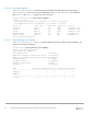
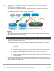
Table Of Contents
- 1 Introduction
- 2 SmartFabric Services for PowerEdge MX: An overview
- 3 SmartFabric mode requirements, guidelines, and restrictions
- 3.1 Create multi-chassis management group
- 3.2 Upstream network requirements
- 3.3 VLAN scaling guidelines
- 3.4 Configuring port speed and breakout
- 3.5 Switch slot placement for SmartFabric mode
- 3.6 Switch-to-Switch cabling
- 3.7 NIC teaming guidelines
- 3.8 Maximum Transmission Unit (MTU) behavior
- 3.9 Other restrictions and guidelines
- 4 Creating a SmartFabric
- 4.1 Physically cable MX chassis and upstream switches
- 4.2 Define VLANs
- 4.3 Create the SmartFabric
- 4.4 Configure uplink port speed or breakout, if needed
- 4.5 Create Ethernet uplink
- 4.6 Configure Fibre Channel universal ports
- 4.7 Create Fibre Channel uplinks
- 4.8 Configuring the upstream switch and connect uplink cables
- 5 Deploying a server
- 6 SmartFabric operations
- 7 Switch operations
- 8 Validating the SmartFabric deployment
- 9 SmartFabric troubleshooting
- 9.1 Troubleshooting errors encountered for port group breakout
- 9.2 Troubleshooting Spanning Tree Protocol (STP)
- 9.3 Verify VLT/vPC configuration on upstream switches
- 9.4 Discovery of FEM and compute sleds
- 9.5 Troubleshooting uplink errors
- 9.6 Troubleshooting FC/FCoE
- 9.7 SmartFabric Services – Troubleshooting commands
- 10 Uplink configuration scenarios
- 10.1 Scenario 1 - SmartFabric deployment with Dell EMC PowerSwitch Z9100-ON upstream switches
- 10.2 Scenario 2 - SmartFabric connected to Cisco Nexus 3232C switches
- 10.3 Scenario 3: Connect MX9116n FSE to Fibre Channel storage - NPIV Proxy Gateway mode
- 10.4 Scenario 4: Connect MX9116n FSE to Fibre Channel storage - FC Direct Attach
- 10.5 Scenario 5: Connect MX5108n to Fibre Channel storage - FSB
- 10.6 Scenario 6: Configure Boot from SAN
- A Hardware used in this document
- B Dell EMC Unity information
- C Additional information
- D Validated components
- E Technical resources
- F Support and feedback

98 Dell EMC PowerEdge MX SmartFabric Configuration and Troubleshooting Guide
vPC status
----------------------------------------------------------------------
id Port Status Consistency Reason Active vlans
-- ---- ------ ----------- ------ ------------
255 Po1 up success success 1,10
10.2.2.2 show vpc consistency-parameters
The show vpc consistency-parameters command displays the configured values on all interfaces
in the vPC. The displayed configurations are only those configurations that limit the vPC peer link and vPC
from coming up.
NX3232C-Leaf1# show vpc consistency-parameters vpc 255
Legend:
Type 1 : vPC will be suspended in case of mismatch
Name Type Local Value Peer Value
------------- ---- ---------------------- -----------------------
STP Port Type 1 Normal Port Normal Port
STP Port Guard 1 Default Default
STP MST Simulate PVST 1 Default Default
lag-id 1 [(1000, [(1000,
20-4-f-0-cd-1e, 1, 0, 20-4-f-0-cd-1e, 1, 0,
0), (7f9b, 0), (7f9b,
0-23-4-ee-be-ff, 80ff, 0-23-4-ee-be-ff, 80ff,
0, 0)] 0, 0)]
mode 1 active active
delayed-lacp 1 disabled disabled
Speed 1 100 Gb/s 100 Gb/s
Duplex 1 full full
Port Mode 1 trunk trunk
Native Vlan 1 1 1
MTU 1 1500 1500
Dot1q Tunnel 1 no no
Switchport Isolated 1 0 0
vPC card type 1 N9K TOR N9K TOR
Allowed VLANs - 1,10 1,10
Local suspended VLANs - - -