
Users Guide
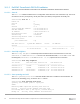
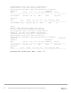

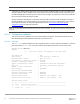
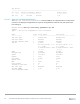
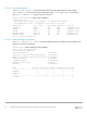
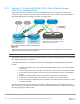
Table Of Contents
- 1 Introduction
- 2 SmartFabric Services for PowerEdge MX: An overview
- 3 SmartFabric mode requirements, guidelines, and restrictions
- 3.1 Create multi-chassis management group
- 3.2 Upstream network requirements
- 3.3 VLAN scaling guidelines
- 3.4 Configuring port speed and breakout
- 3.5 Switch slot placement for SmartFabric mode
- 3.6 Switch-to-Switch cabling
- 3.7 NIC teaming guidelines
- 3.8 Maximum Transmission Unit (MTU) behavior
- 3.9 Other restrictions and guidelines
- 4 Creating a SmartFabric
- 4.1 Physically cable MX chassis and upstream switches
- 4.2 Define VLANs
- 4.3 Create the SmartFabric
- 4.4 Configure uplink port speed or breakout, if needed
- 4.5 Create Ethernet uplink
- 4.6 Configure Fibre Channel universal ports
- 4.7 Create Fibre Channel uplinks
- 4.8 Configuring the upstream switch and connect uplink cables
- 5 Deploying a server
- 6 SmartFabric operations
- 7 Switch operations
- 8 Validating the SmartFabric deployment
- 9 SmartFabric troubleshooting
- 9.1 Troubleshooting errors encountered for port group breakout
- 9.2 Troubleshooting Spanning Tree Protocol (STP)
- 9.3 Verify VLT/vPC configuration on upstream switches
- 9.4 Discovery of FEM and compute sleds
- 9.5 Troubleshooting uplink errors
- 9.6 Troubleshooting FC/FCoE
- 9.7 SmartFabric Services – Troubleshooting commands
- 10 Uplink configuration scenarios
- 10.1 Scenario 1 - SmartFabric deployment with Dell EMC PowerSwitch Z9100-ON upstream switches
- 10.2 Scenario 2 - SmartFabric connected to Cisco Nexus 3232C switches
- 10.3 Scenario 3: Connect MX9116n FSE to Fibre Channel storage - NPIV Proxy Gateway mode
- 10.4 Scenario 4: Connect MX9116n FSE to Fibre Channel storage - FC Direct Attach
- 10.5 Scenario 5: Connect MX5108n to Fibre Channel storage - FSB
- 10.6 Scenario 6: Configure Boot from SAN
- A Hardware used in this document
- B Dell EMC Unity information
- C Additional information
- D Validated components
- E Technical resources
- F Support and feedback
95 Dell EMC PowerEdge MX SmartFabric Configuration and Troubleshooting Guide
10.2.1 Cisco Nexus 3232C switch configuration
The following section outlines the configuration commands issued to the Cisco Nexus 3232C leaf switches.
Note: While this configuration example is specific to the Cisco Nexus 3232C switch, the same concepts apply to
other Cisco Nexus and IOS switches.
The switches start at their factory default settings, as described in Appendix C.4.
Note: The MX IOMs run Rapid per-VLAN Spanning Tree Plus (RPVST+) by default. Ensure the Cisco and Dell
switches are configured to use compatible STP protocols. The mode of STP on the Cisco switch can be set using
the command spanning-tree mode, which is shown below. See Spanning Tree Protocol recommendations for
more information. In this deployment example, default VLAN is VLAN 1 and the created VLAN is VLAN 10. See
Cisco Nexus 3000 Series NX-OS configuration guide for more details.
There are 4 steps to configure the 3232C upstream switches:
1. Set switch hostname, management IP address, enable features and spanning tree
2. Configure vPC between the switches
3. Configure the VLANs
4. Configure the downstream port channels to connect to the MX switches
Enter the following commands to set the hostname, enable required features, and enable RPVST spanning
tree mode. Configure the management interface and default gateway.
Cisco Nexus 3232C Leaf 1
Cisco Nexus 3232C Leaf 2
configure terminal
hostname 3232C-Leaf1
feature vpc
feature lldp
feature lacp
spanning-tree mode rapid-pvst
interface mgmt0
vrf member management
ip address 100.67.162.201/24
vrf context management
ip route 0.0.0.0/0 100.67.162.254
configure terminal
hostname 3232C-Leaf2
feature vpc
feature lldp
feature lacp
spanning-tree mode rapid-pvst
interface mgmt0
vrf member management
ip address 100.67.162.200/24
vrf context management
ip route 0.0.0.0/0 100.67.162.254
Enter the following commands to create a virtual port channel (vPC) domain and assign the keepalive
destination to the peer switch management IP. Then create a port channel for the vPC peer link and assign
the appropriate switchport interfaces.