
Users Guide
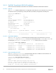
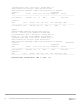

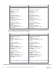
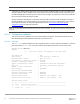
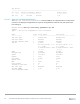
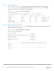
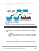
Table Of Contents
- 1 Introduction
- 2 SmartFabric Services for PowerEdge MX: An overview
- 3 SmartFabric mode requirements, guidelines, and restrictions
- 3.1 Create multi-chassis management group
- 3.2 Upstream network requirements
- 3.3 VLAN scaling guidelines
- 3.4 Configuring port speed and breakout
- 3.5 Switch slot placement for SmartFabric mode
- 3.6 Switch-to-Switch cabling
- 3.7 NIC teaming guidelines
- 3.8 Maximum Transmission Unit (MTU) behavior
- 3.9 Other restrictions and guidelines
- 4 Creating a SmartFabric
- 4.1 Physically cable MX chassis and upstream switches
- 4.2 Define VLANs
- 4.3 Create the SmartFabric
- 4.4 Configure uplink port speed or breakout, if needed
- 4.5 Create Ethernet uplink
- 4.6 Configure Fibre Channel universal ports
- 4.7 Create Fibre Channel uplinks
- 4.8 Configuring the upstream switch and connect uplink cables
- 5 Deploying a server
- 6 SmartFabric operations
- 7 Switch operations
- 8 Validating the SmartFabric deployment
- 9 SmartFabric troubleshooting
- 9.1 Troubleshooting errors encountered for port group breakout
- 9.2 Troubleshooting Spanning Tree Protocol (STP)
- 9.3 Verify VLT/vPC configuration on upstream switches
- 9.4 Discovery of FEM and compute sleds
- 9.5 Troubleshooting uplink errors
- 9.6 Troubleshooting FC/FCoE
- 9.7 SmartFabric Services – Troubleshooting commands
- 10 Uplink configuration scenarios
- 10.1 Scenario 1 - SmartFabric deployment with Dell EMC PowerSwitch Z9100-ON upstream switches
- 10.2 Scenario 2 - SmartFabric connected to Cisco Nexus 3232C switches
- 10.3 Scenario 3: Connect MX9116n FSE to Fibre Channel storage - NPIV Proxy Gateway mode
- 10.4 Scenario 4: Connect MX9116n FSE to Fibre Channel storage - FC Direct Attach
- 10.5 Scenario 5: Connect MX5108n to Fibre Channel storage - FSB
- 10.6 Scenario 6: Configure Boot from SAN
- A Hardware used in this document
- B Dell EMC Unity information
- C Additional information
- D Validated components
- E Technical resources
- F Support and feedback

91 Dell EMC PowerEdge MX SmartFabric Configuration and Troubleshooting Guide
Configure the required VLANs on each switch. In this deployment example, the VLAN used is VLAN 10.
Z9100-ON Leaf 1
Z9100-ON Leaf 2
interface vlan10
description “Company A General Purpose”
no shutdown
interface vlan10
description “Company A General Purpose”
no shutdown
Configure the port channels that connect to the downstream switches. The LACP protocol is used to create
the dynamic LAG. Trunk ports allow tagged VLANs to traverse the trunk link. In this example, the trunk is
configured allow VLAN 10.
Z9100-ON Leaf 1
Z9100-ON Leaf 2
interface port-channel1
description "To MX Chassis"
no shutdown
switchport mode trunk
switchport trunk allowed vlan10
vlt-port-channel 1
interface ethernet1/1/1
description "To MX Chassis-1"
no shutdown
no switchport
channel-group 1 mode active
interface ethernet1/1/3
description "To MX Chassis-2"
no shutdown
no switchport
channel-group 1 mode active
end
write memory