
Users Guide
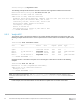
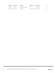

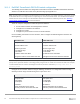
Table Of Contents
- 1 Introduction
- 2 SmartFabric Services for PowerEdge MX: An overview
- 3 SmartFabric mode requirements, guidelines, and restrictions
- 3.1 Create multi-chassis management group
- 3.2 Upstream network requirements
- 3.3 VLAN scaling guidelines
- 3.4 Configuring port speed and breakout
- 3.5 Switch slot placement for SmartFabric mode
- 3.6 Switch-to-Switch cabling
- 3.7 NIC teaming guidelines
- 3.8 Maximum Transmission Unit (MTU) behavior
- 3.9 Other restrictions and guidelines
- 4 Creating a SmartFabric
- 4.1 Physically cable MX chassis and upstream switches
- 4.2 Define VLANs
- 4.3 Create the SmartFabric
- 4.4 Configure uplink port speed or breakout, if needed
- 4.5 Create Ethernet uplink
- 4.6 Configure Fibre Channel universal ports
- 4.7 Create Fibre Channel uplinks
- 4.8 Configuring the upstream switch and connect uplink cables
- 5 Deploying a server
- 6 SmartFabric operations
- 7 Switch operations
- 8 Validating the SmartFabric deployment
- 9 SmartFabric troubleshooting
- 9.1 Troubleshooting errors encountered for port group breakout
- 9.2 Troubleshooting Spanning Tree Protocol (STP)
- 9.3 Verify VLT/vPC configuration on upstream switches
- 9.4 Discovery of FEM and compute sleds
- 9.5 Troubleshooting uplink errors
- 9.6 Troubleshooting FC/FCoE
- 9.7 SmartFabric Services – Troubleshooting commands
- 10 Uplink configuration scenarios
- 10.1 Scenario 1 - SmartFabric deployment with Dell EMC PowerSwitch Z9100-ON upstream switches
- 10.2 Scenario 2 - SmartFabric connected to Cisco Nexus 3232C switches
- 10.3 Scenario 3: Connect MX9116n FSE to Fibre Channel storage - NPIV Proxy Gateway mode
- 10.4 Scenario 4: Connect MX9116n FSE to Fibre Channel storage - FC Direct Attach
- 10.5 Scenario 5: Connect MX5108n to Fibre Channel storage - FSB
- 10.6 Scenario 6: Configure Boot from SAN
- A Hardware used in this document
- B Dell EMC Unity information
- C Additional information
- D Validated components
- E Technical resources
- F Support and feedback
89 Dell EMC PowerEdge MX SmartFabric Configuration and Troubleshooting Guide
10 Uplink configuration scenarios
10.1 Scenario 1 - SmartFabric deployment with Dell EMC PowerSwitch
Z9100-ON upstream switches
Figure 80 shows the production topology using a pair of Dell EMC PowerSwitch Z9100-ONs as upstream
switches. This section walks through configuring the Z9100-ON as well as validating the Z9100-ON
configuration.
18 2014 1610 126 82 4 30 3226 2822 24
17 1913 159 115 71 3 29 3125 2721 23 33SFP+
34SFP+
Stack ID
EST
18 2014 1610 126 82 4 30 3226 2822 24
17 1913 159 115 71 3 29 3125 2721 23 33SFP+
34SFP+
Stack ID
EST
Z9100-ON Leaf 2
Z9100-ON Leaf 1
VLTi (100 GbE)
Fabric uplink (100 GbE)
FSE to FEM (200 GbE)
FSE VLTi (200 GbE)
MX9116n FSE
MX7116n FEM
MX7116n FEM
MX9116n FSE
VLTi
VLTi
SmartFabric with Dell EMC PowerSwitch Z9100-ON leaf switches
Note: See Dell EMC PowerEdge MX Network Architecture Guide for more information on QSFP28-DD cables.