
Users Guide
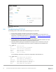
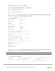
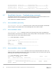
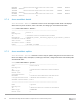


Table Of Contents
- 1 Introduction
- 2 SmartFabric Services for PowerEdge MX: An overview
- 3 SmartFabric mode requirements, guidelines, and restrictions
- 3.1 Create multi-chassis management group
- 3.2 Upstream network requirements
- 3.3 VLAN scaling guidelines
- 3.4 Configuring port speed and breakout
- 3.5 Switch slot placement for SmartFabric mode
- 3.6 Switch-to-Switch cabling
- 3.7 NIC teaming guidelines
- 3.8 Maximum Transmission Unit (MTU) behavior
- 3.9 Other restrictions and guidelines
- 4 Creating a SmartFabric
- 4.1 Physically cable MX chassis and upstream switches
- 4.2 Define VLANs
- 4.3 Create the SmartFabric
- 4.4 Configure uplink port speed or breakout, if needed
- 4.5 Create Ethernet uplink
- 4.6 Configure Fibre Channel universal ports
- 4.7 Create Fibre Channel uplinks
- 4.8 Configuring the upstream switch and connect uplink cables
- 5 Deploying a server
- 6 SmartFabric operations
- 7 Switch operations
- 8 Validating the SmartFabric deployment
- 9 SmartFabric troubleshooting
- 9.1 Troubleshooting errors encountered for port group breakout
- 9.2 Troubleshooting Spanning Tree Protocol (STP)
- 9.3 Verify VLT/vPC configuration on upstream switches
- 9.4 Discovery of FEM and compute sleds
- 9.5 Troubleshooting uplink errors
- 9.6 Troubleshooting FC/FCoE
- 9.7 SmartFabric Services – Troubleshooting commands
- 10 Uplink configuration scenarios
- 10.1 Scenario 1 - SmartFabric deployment with Dell EMC PowerSwitch Z9100-ON upstream switches
- 10.2 Scenario 2 - SmartFabric connected to Cisco Nexus 3232C switches
- 10.3 Scenario 3: Connect MX9116n FSE to Fibre Channel storage - NPIV Proxy Gateway mode
- 10.4 Scenario 4: Connect MX9116n FSE to Fibre Channel storage - FC Direct Attach
- 10.5 Scenario 5: Connect MX5108n to Fibre Channel storage - FSB
- 10.6 Scenario 6: Configure Boot from SAN
- A Hardware used in this document
- B Dell EMC Unity information
- C Additional information
- D Validated components
- E Technical resources
- F Support and feedback

87 Dell EMC PowerEdge MX SmartFabric Configuration and Troubleshooting Guide
Untagged-network :
Networks : e6189b88-7f19-4b05-98b5-0c05ff7ff8c8, 284dae93-b91f-
4593-9cff-c8521cd7ae90
Configured-Interfaces : CBJXLN2:ethernet1/1/42:1, F13RPK2:ethernet1/1/41:1,
F13RPK2:ethernet1/1/42:1, CBJXLN2:ethernet1/1/41:1
----------------------------------------------------------
----------------------------------------------------------
Name : FCoE Path B
Description :
ID : 0f7ad3a2-e59e-4a07-9a74-4e57558f0a4d
Media Type : FC
Native Vlan : 0
Untagged-network :
Networks : e2c35ec5-c177-46f1-9a69-75d8b202d739
Configured-Interfaces : F13RPK2:fibrechannel1/1/44:1,
F13RPK2:fibrechannel1/1/44:2
----------------------------------------------------------
9.7.6 show smartfabric networks
show smartfabric networks command is used to view the various network profile configured. The
command displays the vlans configured, QoS Priority and network type for each network profile.
OS10# show smartfabric networks
Name Type QosPriority Vlan
--------------------------------------------------------------------------------
FCoE A1 STORAGE_FCOE PLATINUM 998
VLAN1 GENERAL_PURPOSE BRONZE 1
FCoE A2 STORAGE_FCOE PLATINUM 999
VLAN10 GENERAL_PURPOSE SILVER 10
UPLINK VLAN GENERAL_PURPOSE SILVER 2491
9.7.7 show smartfabric validation-error
show smartfabric validation-error displays all the information on the validation errors such as
category, sub-category, recommended action, severity, timestamp and recommended link to each error.
9.7.8 show smartfabric nodes
show smartfabric nodes command is used to view the details of the nodes that are part of the cluster.
This command helps the user to view the status of a node, chassis details the node belongs to.
OS10# show smartfabric nodes
Service-Tag Type Status Mode Chassis-Service Chassis-Slot
Tag
--------------------------------------------------------------------------------
---------------------------------------------
F13RPK2 MX9116n ONLINE FABRIC SKY003Z A2
110DXC2 MX7116n NOT-APPLICABLE SKY002Z A2