
Users Guide
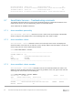
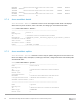
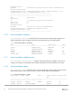

Table Of Contents
- 1 Introduction
- 2 SmartFabric Services for PowerEdge MX: An overview
- 3 SmartFabric mode requirements, guidelines, and restrictions
- 3.1 Create multi-chassis management group
- 3.2 Upstream network requirements
- 3.3 VLAN scaling guidelines
- 3.4 Configuring port speed and breakout
- 3.5 Switch slot placement for SmartFabric mode
- 3.6 Switch-to-Switch cabling
- 3.7 NIC teaming guidelines
- 3.8 Maximum Transmission Unit (MTU) behavior
- 3.9 Other restrictions and guidelines
- 4 Creating a SmartFabric
- 4.1 Physically cable MX chassis and upstream switches
- 4.2 Define VLANs
- 4.3 Create the SmartFabric
- 4.4 Configure uplink port speed or breakout, if needed
- 4.5 Create Ethernet uplink
- 4.6 Configure Fibre Channel universal ports
- 4.7 Create Fibre Channel uplinks
- 4.8 Configuring the upstream switch and connect uplink cables
- 5 Deploying a server
- 6 SmartFabric operations
- 7 Switch operations
- 8 Validating the SmartFabric deployment
- 9 SmartFabric troubleshooting
- 9.1 Troubleshooting errors encountered for port group breakout
- 9.2 Troubleshooting Spanning Tree Protocol (STP)
- 9.3 Verify VLT/vPC configuration on upstream switches
- 9.4 Discovery of FEM and compute sleds
- 9.5 Troubleshooting uplink errors
- 9.6 Troubleshooting FC/FCoE
- 9.7 SmartFabric Services – Troubleshooting commands
- 10 Uplink configuration scenarios
- 10.1 Scenario 1 - SmartFabric deployment with Dell EMC PowerSwitch Z9100-ON upstream switches
- 10.2 Scenario 2 - SmartFabric connected to Cisco Nexus 3232C switches
- 10.3 Scenario 3: Connect MX9116n FSE to Fibre Channel storage - NPIV Proxy Gateway mode
- 10.4 Scenario 4: Connect MX9116n FSE to Fibre Channel storage - FC Direct Attach
- 10.5 Scenario 5: Connect MX5108n to Fibre Channel storage - FSB
- 10.6 Scenario 6: Configure Boot from SAN
- A Hardware used in this document
- B Dell EMC Unity information
- C Additional information
- D Validated components
- E Technical resources
- F Support and feedback

81 Dell EMC PowerEdge MX SmartFabric Configuration and Troubleshooting Guide
switch(config-if)# negotiate auto
The following example shows interface ethernet 1/2 that has auto negotiation enabled on the interface:
Nexus-3232C-Leaf1(config-if)# do show int eth 1/2
Ethernet1/2 is down (XCVR not inserted)
admin state is down, Dedicated Interface
Hardware: 40000/100000 Ethernet, address: 00fe.c8ca.f367 (bia 00fe.c8ca.f36c)
MTU 1500 bytes, BW 100000000 Kbit, DLY 10 usec
reliability 255/255, txload 1/255, rxload 1/255
Encapsulation ARPA, medium is broadcast
auto-duplex, auto-speed
Beacon is turned off
Auto-Negotiation is turned on, FEC mode is Auto
---- OUTPUT TRUNCATED -----
9.5.5 Verify LACP
The interface status of the upstream switches can provide valuable information for the link being down. The
following example shows interfaces 1 and 3 on upstream Cisco Nexus switches as members of port channel
1:
3232C-Leaf2# show interface status
--------------------------------------------------------------------------------
Port Name Status Vlan Duplex Speed Type
--------------------------------------------------------------------------------
mgmt0 -- connected routed full 1000 --
Eth1/1 To MX Chassis 1 suspended trunk full 100G QSFP-100G-SR4
Eth1/2 -- xcvrAbsen routed auto auto --
Eth1/3 To MX Chassis 2 suspended trunk full 100G QSFP-100G-SR4
---- OUTPUT TRUNCATED -----
Checking interface 1 reveals that the ports are not receiving the LACP PDUs as shown in the following
example:
3232C-Leaf2# show int eth 1/1
Ethernet1/1 is down (suspended(no LACP PDUs))
admin state is up, Dedicated Interface
Belongs to Po1
---- OUTPUT TRUNCATED -----
Note: In Dell EMC PowerSwitches, use show interface status command to view the interfaces and
associated status information. Use show interface ethernet interface number to view the interface
details.
In this example, the errors listed above occurred because an uplink was not created on the fabric.