
Users Guide
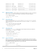
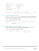

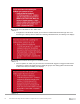
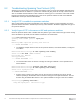
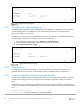
Table Of Contents
- 1 Introduction
- 2 SmartFabric Services for PowerEdge MX: An overview
- 3 SmartFabric mode requirements, guidelines, and restrictions
- 3.1 Create multi-chassis management group
- 3.2 Upstream network requirements
- 3.3 VLAN scaling guidelines
- 3.4 Configuring port speed and breakout
- 3.5 Switch slot placement for SmartFabric mode
- 3.6 Switch-to-Switch cabling
- 3.7 NIC teaming guidelines
- 3.8 Maximum Transmission Unit (MTU) behavior
- 3.9 Other restrictions and guidelines
- 4 Creating a SmartFabric
- 4.1 Physically cable MX chassis and upstream switches
- 4.2 Define VLANs
- 4.3 Create the SmartFabric
- 4.4 Configure uplink port speed or breakout, if needed
- 4.5 Create Ethernet uplink
- 4.6 Configure Fibre Channel universal ports
- 4.7 Create Fibre Channel uplinks
- 4.8 Configuring the upstream switch and connect uplink cables
- 5 Deploying a server
- 6 SmartFabric operations
- 7 Switch operations
- 8 Validating the SmartFabric deployment
- 9 SmartFabric troubleshooting
- 9.1 Troubleshooting errors encountered for port group breakout
- 9.2 Troubleshooting Spanning Tree Protocol (STP)
- 9.3 Verify VLT/vPC configuration on upstream switches
- 9.4 Discovery of FEM and compute sleds
- 9.5 Troubleshooting uplink errors
- 9.6 Troubleshooting FC/FCoE
- 9.7 SmartFabric Services – Troubleshooting commands
- 10 Uplink configuration scenarios
- 10.1 Scenario 1 - SmartFabric deployment with Dell EMC PowerSwitch Z9100-ON upstream switches
- 10.2 Scenario 2 - SmartFabric connected to Cisco Nexus 3232C switches
- 10.3 Scenario 3: Connect MX9116n FSE to Fibre Channel storage - NPIV Proxy Gateway mode
- 10.4 Scenario 4: Connect MX9116n FSE to Fibre Channel storage - FC Direct Attach
- 10.5 Scenario 5: Connect MX5108n to Fibre Channel storage - FSB
- 10.6 Scenario 6: Configure Boot from SAN
- A Hardware used in this document
- B Dell EMC Unity information
- C Additional information
- D Validated components
- E Technical resources
- F Support and feedback

78 Dell EMC PowerEdge MX SmartFabric Configuration and Troubleshooting Guide
9.3 Verify VLT/vPC configuration on upstream switches
Configuring a single VLT domain with Dell EMC upstream switches or a single vPC domain with Cisco
upstream switches is required. Creating two VLT/vPC domains may cause a network loop. See Scenario 1
and Scenario 2 for the topology used in the deployment example.
The following example shows a mismatch of the VLT domain IDs on VLT peer switches. To resolve this issue,
ensure that a single VLT domain is used across the VLT peers.
Z9100-Leaf1# show vlt 1
Domain ID : 1
Unit ID : 1
Role : primary
Version : 1.0
Local System MAC address : 4c:76:25:e8:f2:c0
Z9100-Leaf2# show vlt 30
Domain ID : 30
Unit ID : 1
Role : primary
Version : 1.0
The following example shows a mismatch of the vPC domain IDs on vPC peer switches. To resolve this
issue, ensure that a single vPC domain is used across the vPC peers.
Nexus-3232C-Leaf1# show vpc
Legend:
(*) - local vPC is down, forwarding via vPC peer-link
vPC domain id : 1
Peer status : peer link is down
vPC keep-alive status : peer is alive, but domain IDs do not match
---- OUTPUT TRUNCATED -----
3232C-Leaf2# show vpc
Legend:
(*) - local vPC is down, forwarding via vPC peer-link
vPC domain id : 255
Peer status : peer link is down
vPC keep-alive status : peer is alive, but domain IDs do not match
---- OUTPUT TRUNCATED -----
9.4 Discovery of FEM and compute sleds
The following can be verified if server or FEM discovery doesn’t happen:
• If there is no link indicated on the FSE port, toggle the auto-negotiation settings for that port.
• Ensure that the compute sled is properly seated in the compute slot in the MX chassis.
• Make sure that the compute sled is turned on.