
Users Guide
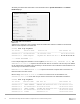
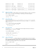
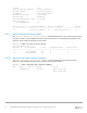

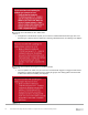
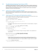
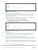
Table Of Contents
- 1 Introduction
- 2 SmartFabric Services for PowerEdge MX: An overview
- 3 SmartFabric mode requirements, guidelines, and restrictions
- 3.1 Create multi-chassis management group
- 3.2 Upstream network requirements
- 3.3 VLAN scaling guidelines
- 3.4 Configuring port speed and breakout
- 3.5 Switch slot placement for SmartFabric mode
- 3.6 Switch-to-Switch cabling
- 3.7 NIC teaming guidelines
- 3.8 Maximum Transmission Unit (MTU) behavior
- 3.9 Other restrictions and guidelines
- 4 Creating a SmartFabric
- 4.1 Physically cable MX chassis and upstream switches
- 4.2 Define VLANs
- 4.3 Create the SmartFabric
- 4.4 Configure uplink port speed or breakout, if needed
- 4.5 Create Ethernet uplink
- 4.6 Configure Fibre Channel universal ports
- 4.7 Create Fibre Channel uplinks
- 4.8 Configuring the upstream switch and connect uplink cables
- 5 Deploying a server
- 6 SmartFabric operations
- 7 Switch operations
- 8 Validating the SmartFabric deployment
- 9 SmartFabric troubleshooting
- 9.1 Troubleshooting errors encountered for port group breakout
- 9.2 Troubleshooting Spanning Tree Protocol (STP)
- 9.3 Verify VLT/vPC configuration on upstream switches
- 9.4 Discovery of FEM and compute sleds
- 9.5 Troubleshooting uplink errors
- 9.6 Troubleshooting FC/FCoE
- 9.7 SmartFabric Services – Troubleshooting commands
- 10 Uplink configuration scenarios
- 10.1 Scenario 1 - SmartFabric deployment with Dell EMC PowerSwitch Z9100-ON upstream switches
- 10.2 Scenario 2 - SmartFabric connected to Cisco Nexus 3232C switches
- 10.3 Scenario 3: Connect MX9116n FSE to Fibre Channel storage - NPIV Proxy Gateway mode
- 10.4 Scenario 4: Connect MX9116n FSE to Fibre Channel storage - FC Direct Attach
- 10.5 Scenario 5: Connect MX5108n to Fibre Channel storage - FSB
- 10.6 Scenario 6: Configure Boot from SAN
- A Hardware used in this document
- B Dell EMC Unity information
- C Additional information
- D Validated components
- E Technical resources
- F Support and feedback

74 Dell EMC PowerEdge MX SmartFabric Configuration and Troubleshooting Guide
Version : 1.0
Local System MAC address : 20:04:0f:00:b8:1e
VLT MAC address : 20:04:0f:00:b8:1e
IP address : fda5:74c8:b79e:1::1
Delay-Restore timer : 90 seconds
Peer-Routing : Disabled
Peer-Routing-Timeout timer : 0 seconds
VLTi Link Status
port-channel1000 : up
VLT Peer Unit ID System MAC Address Status IP Address Version
--------------------------------------------------------------------------------
2 20:04:0f:00:9d:1e up fda5:74c8:b79e:1::2 1.0
8.4.9 show vlt domain-id vlt-port-detail
The show vlt domain-id vlt-port-detail command shows the VLT port channel status for both
VLT peers. The VLT in this example is connected to the Cisco ACI vPC. It is automatically configured in port
channel 1, and it consists of two ports on each switch.
MX9116n-1# show vlt 255 vlt-port-detail
vlt-port-channel ID : 1
VLT Unit ID Port-Channel Status Configured ports Active ports
-------------------------------------------------------------------------------
* 1 port-channel1 up 2 2
2 port-channel1 up 2 2
8.4.10 show interface port channel summary
The show interface port-channel summary command shows the LAG number (VLT port
channel 1 in this example), the mode, status and ports used in the port channel.
MX9116n-1# show interface port-channel summary
LAG Mode Status Uptime Ports
1 L2-HYBRID up 00:29:20 Eth 1/1/43 (Up)
Eth 1/1/44 (Up)