
Users Guide
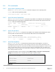
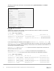
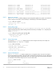
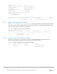

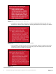
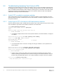
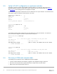
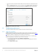
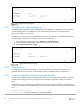
Table Of Contents
- 1 Introduction
- 2 SmartFabric Services for PowerEdge MX: An overview
- 3 SmartFabric mode requirements, guidelines, and restrictions
- 3.1 Create multi-chassis management group
- 3.2 Upstream network requirements
- 3.3 VLAN scaling guidelines
- 3.4 Configuring port speed and breakout
- 3.5 Switch slot placement for SmartFabric mode
- 3.6 Switch-to-Switch cabling
- 3.7 NIC teaming guidelines
- 3.8 Maximum Transmission Unit (MTU) behavior
- 3.9 Other restrictions and guidelines
- 4 Creating a SmartFabric
- 4.1 Physically cable MX chassis and upstream switches
- 4.2 Define VLANs
- 4.3 Create the SmartFabric
- 4.4 Configure uplink port speed or breakout, if needed
- 4.5 Create Ethernet uplink
- 4.6 Configure Fibre Channel universal ports
- 4.7 Create Fibre Channel uplinks
- 4.8 Configuring the upstream switch and connect uplink cables
- 5 Deploying a server
- 6 SmartFabric operations
- 7 Switch operations
- 8 Validating the SmartFabric deployment
- 9 SmartFabric troubleshooting
- 9.1 Troubleshooting errors encountered for port group breakout
- 9.2 Troubleshooting Spanning Tree Protocol (STP)
- 9.3 Verify VLT/vPC configuration on upstream switches
- 9.4 Discovery of FEM and compute sleds
- 9.5 Troubleshooting uplink errors
- 9.6 Troubleshooting FC/FCoE
- 9.7 SmartFabric Services – Troubleshooting commands
- 10 Uplink configuration scenarios
- 10.1 Scenario 1 - SmartFabric deployment with Dell EMC PowerSwitch Z9100-ON upstream switches
- 10.2 Scenario 2 - SmartFabric connected to Cisco Nexus 3232C switches
- 10.3 Scenario 3: Connect MX9116n FSE to Fibre Channel storage - NPIV Proxy Gateway mode
- 10.4 Scenario 4: Connect MX9116n FSE to Fibre Channel storage - FC Direct Attach
- 10.5 Scenario 5: Connect MX5108n to Fibre Channel storage - FSB
- 10.6 Scenario 6: Configure Boot from SAN
- A Hardware used in this document
- B Dell EMC Unity information
- C Additional information
- D Validated components
- E Technical resources
- F Support and feedback
72 Dell EMC PowerEdge MX SmartFabric Configuration and Troubleshooting Guide
Alternately the iDRAC MAC information can be obtained from the System Information on the iDRAC
Dashboard page.
IOM Port Information
Subsequently, viewing the LLDP neighbors shows the iDRAC MAC address in addition to the NIC MAC
address of the respective mezzanine card.
C160A1# show lldp neighbors
Loc PortID Rem Host Name Rem Port Id Rem Chassis Id
--------------------------------------------------------------------------------
ethernet1/1/1 Not Advertised 98:03:9b:65:73:b2 98:03:9b:65:73:b4
ethernet1/1/1 iDRAC-8XQP0T2 8XQP0T2 NIC.Mezzanine.1A-1-1 d0:94:66:87:ab:40
---- OUTPUT TRUNCATED -----
In the example deployment validation of LLDP neighbors, Ethernet1/1/1, ethernet 1/1/3, and
ethernet 1/1/71-1/1/72 represent the two MX740c sleds in one chassis. The first entry is the iDRAC
for the compute sled. The iDRAC uses connectivity to the mezzanine card to advertise LLDP information. The
second entry is the mezzanine card itself.
Ethernet 1/71/1 and ethernet 1/71/2 represent the MX740c compute sleds connected to the
MX7116n FEM in the other chassis.
Ethernet range ethernet1/1/37-1/1/40 are the VLTi interfaces for the SmartFabric. Last,
ethernet1/1/41-1/1/42 are the links in a port channel connected to the Z9100-ON leaf switches.
C140A1# show lldp neighbors
Loc PortID Rem Host Name Rem Port Id Rem Chassis Id
----------------------------------------------------------------------------
ethernet1/1/1 iDRAC-CBMP9N2 CBMP9N2 NIC.Mezzanine.1A-1-1 d0:94:66:2a:07:2f
ethernet1/1/1 Not Advertised 24:6e:96:9c:e3:50 24:6e:96:9c:e3:50
ethernet1/1/3 iDRAC-1S35MN2 1S35MN2 NIC.Mezzanine.1A-1-1 d0:94:66:29:fa:f4
ethernet1/1/3 Not Advertised 24:6e:96:9c:e5:48 24:6e:96:9c:e5:48
ethernet1/1/37 C160A2 ethernet1/1/37 20:04:0f:00:a1:9e