
Users Guide
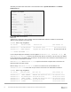
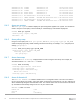
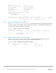

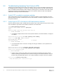
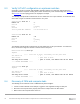
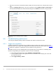
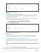
Table Of Contents
- 1 Introduction
- 2 SmartFabric Services for PowerEdge MX: An overview
- 3 SmartFabric mode requirements, guidelines, and restrictions
- 3.1 Create multi-chassis management group
- 3.2 Upstream network requirements
- 3.3 VLAN scaling guidelines
- 3.4 Configuring port speed and breakout
- 3.5 Switch slot placement for SmartFabric mode
- 3.6 Switch-to-Switch cabling
- 3.7 NIC teaming guidelines
- 3.8 Maximum Transmission Unit (MTU) behavior
- 3.9 Other restrictions and guidelines
- 4 Creating a SmartFabric
- 4.1 Physically cable MX chassis and upstream switches
- 4.2 Define VLANs
- 4.3 Create the SmartFabric
- 4.4 Configure uplink port speed or breakout, if needed
- 4.5 Create Ethernet uplink
- 4.6 Configure Fibre Channel universal ports
- 4.7 Create Fibre Channel uplinks
- 4.8 Configuring the upstream switch and connect uplink cables
- 5 Deploying a server
- 6 SmartFabric operations
- 7 Switch operations
- 8 Validating the SmartFabric deployment
- 9 SmartFabric troubleshooting
- 9.1 Troubleshooting errors encountered for port group breakout
- 9.2 Troubleshooting Spanning Tree Protocol (STP)
- 9.3 Verify VLT/vPC configuration on upstream switches
- 9.4 Discovery of FEM and compute sleds
- 9.5 Troubleshooting uplink errors
- 9.6 Troubleshooting FC/FCoE
- 9.7 SmartFabric Services – Troubleshooting commands
- 10 Uplink configuration scenarios
- 10.1 Scenario 1 - SmartFabric deployment with Dell EMC PowerSwitch Z9100-ON upstream switches
- 10.2 Scenario 2 - SmartFabric connected to Cisco Nexus 3232C switches
- 10.3 Scenario 3: Connect MX9116n FSE to Fibre Channel storage - NPIV Proxy Gateway mode
- 10.4 Scenario 4: Connect MX9116n FSE to Fibre Channel storage - FC Direct Attach
- 10.5 Scenario 5: Connect MX5108n to Fibre Channel storage - FSB
- 10.6 Scenario 6: Configure Boot from SAN
- A Hardware used in this document
- B Dell EMC Unity information
- C Additional information
- D Validated components
- E Technical resources
- F Support and feedback
71 Dell EMC PowerEdge MX SmartFabric Configuration and Troubleshooting Guide
8.4 CLI commands
8.4.1 show switch-operating-mode
Use the show switch-operating-mode command to display the current operating mode:
C140A1# show switch-operating-mode
Switch-Operating-Mode : Smart Fabric Mode
8.4.2 show discovered-expanders
The show discovered-expanders command is only available on the MX9116n FSE and displays the
MX7116n FEMs service tag attached to the MX9116n FSEs and the associated port-group and virtual slot.
C140A1# show discovered-expanders
Service Model Type Chassis Chassis-slot Port-group Virtual
tag service-tag Slot-Id
--------------------------------------------------------------------------
D10DXC2 MX7116n 1 SKY002Z A1 1/1/1 71
FEM
8.4.3 show unit-provision
The show unit-provision command is only available on the MX9116n FSE and displays the unit ID
and the provision and discovered name of the MX7116n FEM attached to the MX9116n FSE.
C140A1# show unit-provision
Node ID | Unit ID | Provision Name | Discovered Name | State |
---------+---------+---------------------------------+-------|
1 | 71 | D10DXC2 | D10DXC2 | up |
8.4.4 show lldp neighbors
The show lldp neighbors command shows information about LLDP neighbors. The iDRAC in
PowerEdge MX compute sleds produce LLDP topology packets that contain specific information that the
SmartFabric Services engine uses to determine the physical network topology regardless if a switch is in Full
Switch or SmartFabric modes. For servers connected to switches in SmartFabric mode, the iDRAC LLDP
topology feature is required. Without it, the fabric will not recognize the compute sled and the user will not be
able to deploy networks to the sled.
The iDRAC MAC address can be verified by selecting iDRAC Settings > Overview > Current Network
Settings from the iDRAC GUI of a compute sled. An example is shown as follows:
IOM Port Information