
Users Guide
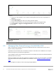
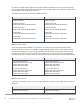
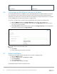
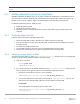

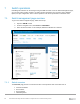
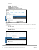
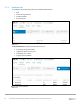

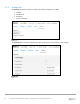
Table Of Contents
- 1 Introduction
- 2 SmartFabric Services for PowerEdge MX: An overview
- 3 SmartFabric mode requirements, guidelines, and restrictions
- 3.1 Create multi-chassis management group
- 3.2 Upstream network requirements
- 3.3 VLAN scaling guidelines
- 3.4 Configuring port speed and breakout
- 3.5 Switch slot placement for SmartFabric mode
- 3.6 Switch-to-Switch cabling
- 3.7 NIC teaming guidelines
- 3.8 Maximum Transmission Unit (MTU) behavior
- 3.9 Other restrictions and guidelines
- 4 Creating a SmartFabric
- 4.1 Physically cable MX chassis and upstream switches
- 4.2 Define VLANs
- 4.3 Create the SmartFabric
- 4.4 Configure uplink port speed or breakout, if needed
- 4.5 Create Ethernet uplink
- 4.6 Configure Fibre Channel universal ports
- 4.7 Create Fibre Channel uplinks
- 4.8 Configuring the upstream switch and connect uplink cables
- 5 Deploying a server
- 6 SmartFabric operations
- 7 Switch operations
- 8 Validating the SmartFabric deployment
- 9 SmartFabric troubleshooting
- 9.1 Troubleshooting errors encountered for port group breakout
- 9.2 Troubleshooting Spanning Tree Protocol (STP)
- 9.3 Verify VLT/vPC configuration on upstream switches
- 9.4 Discovery of FEM and compute sleds
- 9.5 Troubleshooting uplink errors
- 9.6 Troubleshooting FC/FCoE
- 9.7 SmartFabric Services – Troubleshooting commands
- 10 Uplink configuration scenarios
- 10.1 Scenario 1 - SmartFabric deployment with Dell EMC PowerSwitch Z9100-ON upstream switches
- 10.2 Scenario 2 - SmartFabric connected to Cisco Nexus 3232C switches
- 10.3 Scenario 3: Connect MX9116n FSE to Fibre Channel storage - NPIV Proxy Gateway mode
- 10.4 Scenario 4: Connect MX9116n FSE to Fibre Channel storage - FC Direct Attach
- 10.5 Scenario 5: Connect MX5108n to Fibre Channel storage - FSB
- 10.6 Scenario 6: Configure Boot from SAN
- A Hardware used in this document
- B Dell EMC Unity information
- C Additional information
- D Validated components
- E Technical resources
- F Support and feedback
51 Dell EMC PowerEdge MX SmartFabric Configuration and Troubleshooting Guide
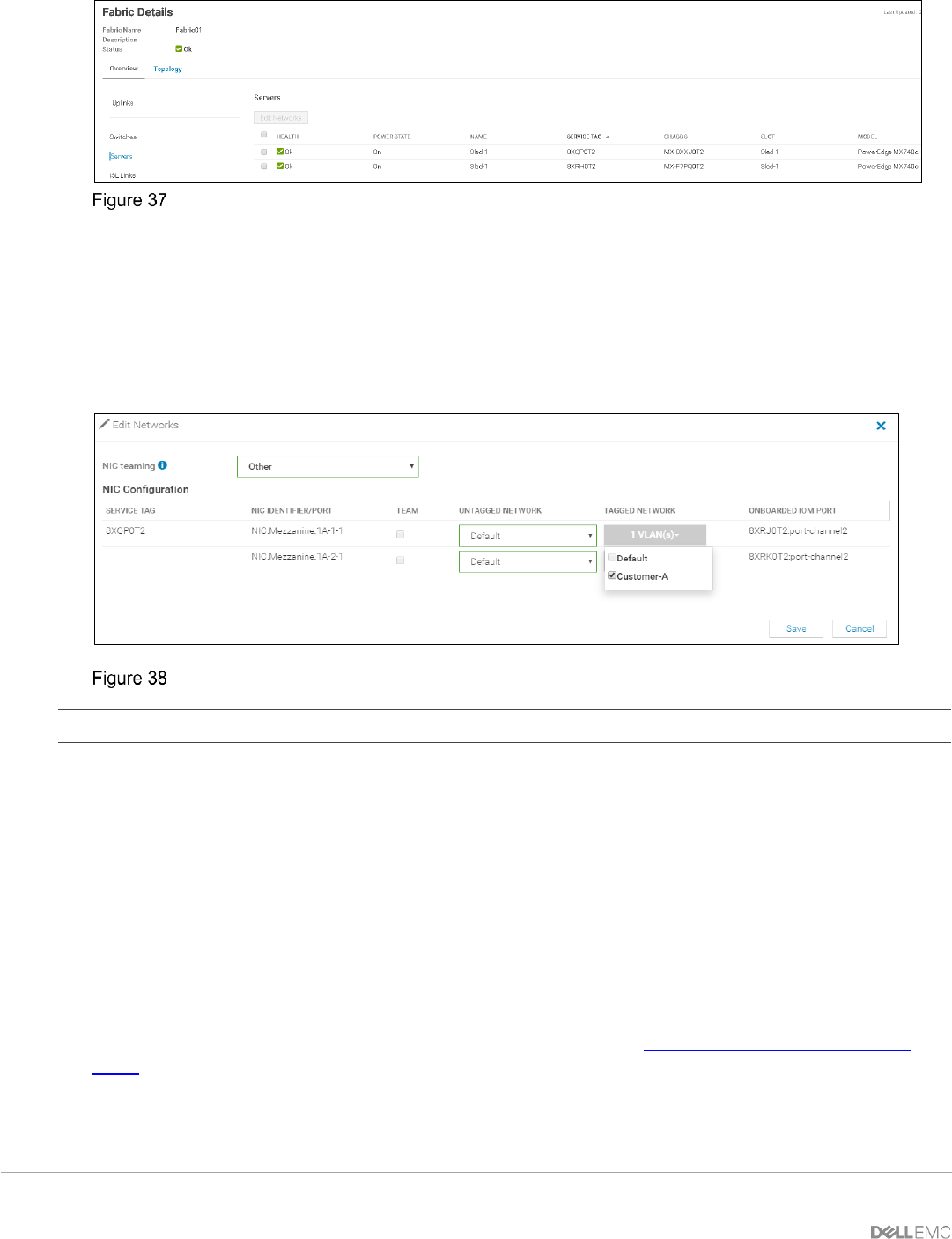
Add/remove VLANs
5. Choose the desired server. In this example PowerEdge MX740C with service tag 8XQP0T2 is
selected.
6. Choose Edit Networks.
7. Choose NIC teaming from LACP, No Teaming and Other options.
8. Modify the VLAN selections as required by defining the tagged and untagged VLANs.
9. Select VLANs on Tagged and Untagged Network for each Mezzanine card port.
10. Click Save.
Modify VLANs
Note: At this time, only one server can be selected at a time in the GUI.
6.5 Managing Fibre Channel Zoning on the MX9116n FSE
When a storage array is directly connected to the MX9116n FSE, Fibre Channel Zones can be used to
improve security and performance.
Preparation of servers will be same as mentioned in Section 5. Determine the FC WWPNs for the compute
sleds and storage array as discussed in Appendix B.
These examples assume that the storage array has been successfully connected to the MX9116n FSE’s FC
uplinks and there are no errors.
Below are examples of the steps and commands to configure FC Zoning. For more information on Dell EMC
SmartFabric OS10 Fibre Channel capabilities and commands, see the Dell EMC SmartFabric OS10 User
Guide.
Step 1: Configure FC aliases for server and storage adapter WWPNs.