
Users Guide
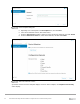
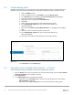
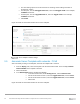
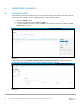
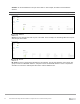
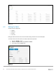
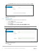
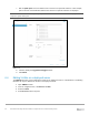
Table Of Contents
- 1 Introduction
- 2 SmartFabric Services for PowerEdge MX: An overview
- 3 SmartFabric mode requirements, guidelines, and restrictions
- 3.1 Create multi-chassis management group
- 3.2 Upstream network requirements
- 3.3 VLAN scaling guidelines
- 3.4 Configuring port speed and breakout
- 3.5 Switch slot placement for SmartFabric mode
- 3.6 Switch-to-Switch cabling
- 3.7 NIC teaming guidelines
- 3.8 Maximum Transmission Unit (MTU) behavior
- 3.9 Other restrictions and guidelines
- 4 Creating a SmartFabric
- 4.1 Physically cable MX chassis and upstream switches
- 4.2 Define VLANs
- 4.3 Create the SmartFabric
- 4.4 Configure uplink port speed or breakout, if needed
- 4.5 Create Ethernet uplink
- 4.6 Configure Fibre Channel universal ports
- 4.7 Create Fibre Channel uplinks
- 4.8 Configuring the upstream switch and connect uplink cables
- 5 Deploying a server
- 6 SmartFabric operations
- 7 Switch operations
- 8 Validating the SmartFabric deployment
- 9 SmartFabric troubleshooting
- 9.1 Troubleshooting errors encountered for port group breakout
- 9.2 Troubleshooting Spanning Tree Protocol (STP)
- 9.3 Verify VLT/vPC configuration on upstream switches
- 9.4 Discovery of FEM and compute sleds
- 9.5 Troubleshooting uplink errors
- 9.6 Troubleshooting FC/FCoE
- 9.7 SmartFabric Services – Troubleshooting commands
- 10 Uplink configuration scenarios
- 10.1 Scenario 1 - SmartFabric deployment with Dell EMC PowerSwitch Z9100-ON upstream switches
- 10.2 Scenario 2 - SmartFabric connected to Cisco Nexus 3232C switches
- 10.3 Scenario 3: Connect MX9116n FSE to Fibre Channel storage - NPIV Proxy Gateway mode
- 10.4 Scenario 4: Connect MX9116n FSE to Fibre Channel storage - FC Direct Attach
- 10.5 Scenario 5: Connect MX5108n to Fibre Channel storage - FSB
- 10.6 Scenario 6: Configure Boot from SAN
- A Hardware used in this document
- B Dell EMC Unity information
- C Additional information
- D Validated components
- E Technical resources
- F Support and feedback
46 Dell EMC PowerEdge MX SmartFabric Configuration and Troubleshooting Guide
6 SmartFabric operations
6.1 Viewing the fabric
A SmartFabric is viewed using OME-M. The green check mark adjacent to the fabric name informs that the
status of the fabric is healthy. In this example, the fabric created is named Fabric01.
1. Open the OME-M console.
2. From the navigation menu, click Devices > Fabric.
3. To view the Fabric components, select the fabric. This can also be achieved by clicking the View
Details button the right.
SmartFabric
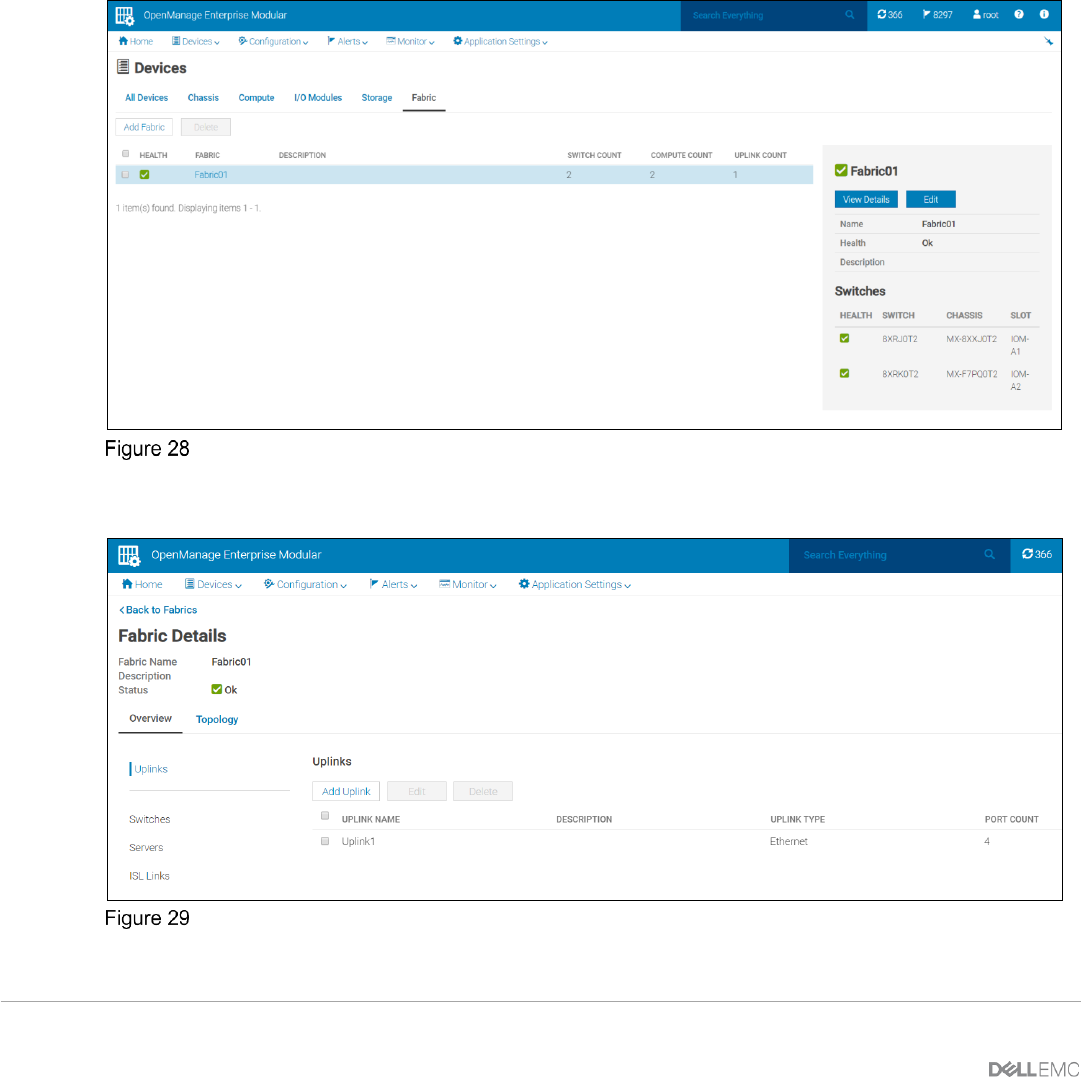
Fabric components include Uplinks, Switches, Servers and ISL Links. Uplinks connect the MX9116n
switches with upstream switches. In this example, the uplink is named as Uplink1.
Uplinks